66
NOTE: If the needle bearing is washed, re-pack the
bearing with hi-temp molybdenum wheel bearing
grease.
2. Remove any drive belt dust accumulation from the
stationary sheave, movable sheave, and bushings
using parts-cleaning solvent only.
3. Inspect stationary sheave, movable sheave, spider,
and cover for cracks or imperfections in the casting.
4. Inspect the cam arm pins for wear or bends.
5. Inspect the bushing in the cover for wear, damage, or
cracks.
6. Inspect the bushing in the movable sheave for wear,
damage, or cracks.
7. Inspect the spring for cracking or twisting.
8. Inspect all threaded areas for any cracked or stripped
threads.
9. Inspect the roller bushings for damage or fraying.
10. Inspect the needle bearings for missing needles or
torn or missing seals.
11. Inspect the stationary sheave and shaft for damage or
wear.
Assembling
NOTE: Steps 1-6 are for models with a shift stop
only. For models with a nut, proceed to step 7.
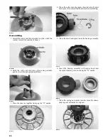
1. Place the cam arms, thrust washers, and cam arm
pivot pins (pivot pin heads opposite direction of rota-
tion) into the moveable drive sheave and secure with
new lock nuts. Tighten to 48 in.-lb.
NOTE: The drive clutch rotates clockwise.
2. Align the spider and movable sheave timing marks;
then making sure the cam arms are properly posi-
tioned, drop the spider into position in the moveable
sheave.
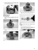
3. Place the movable sheave, spacer washers, and spi-
der into position on the stationary sheave hub. Make
sure all threads are clean and free of oily residue.
Apply Loctite Primer #7649 and allow to dry per
instructions; then apply red Loctite #277 to the
threads of the stationary sheave and spider. Tighten
the spider to 265 ft-lb.
WC641
WC642
NOTE: Allow the Loctite to cure at room tempera-
ture for 24 hours.
NOTE: Grasp the moveable sheave and lift it
upward; then release it. It must move freely and not
bind at any point.
4. With the head of each cam arm pin positioned away
from the direction of the drive clutch rotation, install
the cam arms.
NOTE: The drive clutch rotates clockwise.
5. Secure the cam arm pins with new lock nuts and
tighten to 48 in.-lb.
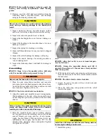
6. Place the shift stop into position with the relief
towards the spider.
WC655
7. Install the spring.
CAUTION
Do not use steel wool or a wire brush to clean compo-
nents having a bushing; damage to the bushing will
result.
! WARNING
Never reuse the lock nuts on the cam arm pins.
CAUTION
Failure to align the spider and movable sheave timing
marks will cause drive clutch to be out of balance
resulting in clutch and crankshaft damage.
CAUTION
Install the shift stop cam with the relief facing down or
severe engine damage could occur.


