67
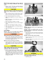
8. Align the match marks (X) and install the clutch
cover and secure with six cap screws. Tighten using
a crisscross pattern to 120 in.-lb.
WC653A
DRIVEN CLUTCH
Disassembling
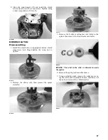
1. Install the clutch into an appropriate driven clutch
compressor tool. Finger-tighten the wing nut to
tighten.
WC638
2. Remove the driven cam; then remove the spider
assembly.
WC636
WC635
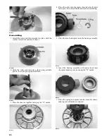
3. Remove the E-clips securing the cam rollers to the
spider; then remove the thrust washer and roller.
WC628
NOTE: The relief in the roller is directed towards
the spider.
4. Remove the spring and movable sheave.
5. Using a suitable punch, remove the roller pin secur-
ing the roller axle in movable sheave; then drive out
the axle and account for a thrust washer.
WC627


