71
WC809
WC667
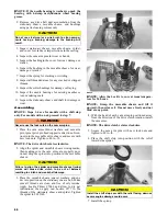
7. Making sure the “X” marks are properly aligned,
install the movable drive sheave and secure with the
cap screw (A), washer (B), and shim(s) (C). Tighten
to 60 ft-lb.
WC741A
8. Place the transmission in neutral and rotate the
driven clutch and drive belt by hand in a clockwise
direction for three complete revolutions.
NOTE: Do not rotate in a counter clockwise direc-
tion as this will produce an inaccurate reading.
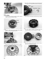
9. Verify 0.8 mm (0.030”) clearance between stationary
sheave on drive clutch and drive belt by using a
feeler gauge flat against the sheave. Check for slight
resistance with gauge between sheave and belt.
WC739
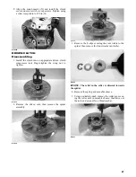
10. If offset adjustment is necessary, place the transmis-
sion in park. Remove the driven clutch cap screw
(A), washer (B), and any shims (C). If belt clearance
is too small, add additional shims to gain the desired
clearance. If belt clearance is too large, remove
shims to gain the desired clearance.
11. Install the cap screw (A), washer (B), and shim(s)
(C). Tighten the screw to 60 ft-lb.
12. Repeat steps 8-11 until proper clearance is achieved.
13. Place the CVT cover gasket into position; then with
the two alignment pins in position, install the cover
and secure with the cap screws. Tighten the cap
screws to 8 ft-lb.
Center Crankcase
Components
NOTE: This procedure cannot be done with the
engine/transmission in the frame. Complete Remov-
ing procedures for Top-Side, Left-Side, and
Right-Side must precede this procedure.
NOTE: For efficiency, it is preferable to remove and
disassemble only those components which need to be
addressed and to service only those components. The
technician should use discretion and sound judgment.
Separating Crankcase
Halves
1. Remove the oil strainer cap; then remove the oil
strainer.


