background image

Our Customer service staff is available to help you. For any problem with your purchase, or to receive further 

information about this product, please call our toll-free number.

SAVE THIS MANUAL

Keep this manual and the original sales invoice in a safe, dry place for future reference.

Notre personnel du service à la clientèle est disponible pour vous aider. En cas de problème avec votre achat, ou pour 

obtenir plus d’informations à propos de ce produit,  veuillez composer notre numéro sans frais.

CONSERVEZ CE GUIDE

Conservez ce manuel avec la facture d’origine dans un endroit sûr et sec pour référence future.

PORTABLE AIR CONDITIONER

Operator's manual

Customer Service / Service à la clientèle: 

Model/modèle : 87795054
                           MPPD-12CRN1-BI0

1-866-206-0888

Summary of Contents for 87795054

Page 1: ...re reference Notre personnel du service la client le est disponible pour vous aider En cas de probl me avec votre achat ou pour obtenir plus d informations propos de ce produit veuillez composer notre...

Page 2: ...Precautions 3 Cautions 4 Installation 5 Operation 9 Maintenance 14 Faults Diagnosis 15 Design and Compliance Notes 16 Sociable Remarks 17 Remote Controller Illustration 18 Air Conditioner Limited War...

Page 3: ...louver blade swing automatically Caster Power plug socket Power cord buckle Bottom tray drain outlet Power cord outlet Drain outlet only for pump heating mode Upper air filter behind the grille Upper...

Page 4: ...y room Excessive exposure to water can cause electrical components to short circuit DO NOT install the unit in a location that may be exposed to combustible gas as this could cause re The unit has whe...

Page 5: ...to avoid a hazard Prior to cleaning or any other maintenance the appliance must be disconnected from the supply mains Do not install the appliance in a location that may be exposed to combustible gas...

Page 6: ...rmation on the type of gas and the amount please refer to the relevant label on the unit itself Installation service maintenance and repair of this unit must be performed by a certi ed technician Prod...

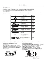
Page 7: ...with the hole seat of the air outlet and slide down the exhaust hose assembly along the arrow direction for installation Step 2 Installing the Exhaust Hose Assembly to the Unit Part Description 1 pc 1...

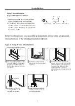
Page 8: ...s and attach them to the window sash and frame as shown Insert the window slider assembly into the window opening Insert the window slider adaptor into the hole of the window slider Cut the non adhesi...

Page 9: ...the window frame to prevent air and insects from getting into the room Type 2 Sliding Window Installation Note To ensure proper function DO NOT overextend or bend the hose Make sure that there is no o...

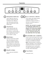
Page 10: ...djust increasing decreasing temperature settings in 1 C 1 F increments in a range of 17 C 62 F to 30 C 86 F or the TIMER setting in a range of 0 24 hrs NOTE The control is capable of displaying temper...

Page 11: ...ll for service Press the MODE button until the COOL indicator light comes on Press the ADJUST buttons or to select your desired room temperature The temperature can be set within a range of 17 C 30 C...

Page 12: ...ontinue to operate as originally programmed SLEEP ECO Operation When the unit is on pressing the TIMER button initiates the Auto off stop program and the TIMER OFF indicator light illuminates Press th...

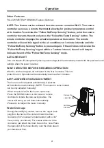
Page 13: ...pper drain plug from the back of the unit and install the drain connector 5 8 universal female mender with a 3 4 hose locally purchased For models without a drain connector just attach the drain hose...

Page 14: ...ion remove the bottom drain plug and let the water drain away Reinstall the bottom drain plug and restart the machine until the P1 symbol disappears If the error repeats call for service NOTE Make sur...

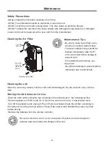
Page 15: ...ety Precautions Clean the unit using a damp lint free cloth and mild detergent Dry the unit with a dry lint free cloth Cleaning the unit Drain the unit s water collection tray according to the instruc...

Page 16: ...caused by the flow of refrigerant inside the unit The air filter is blocked with dust or animal hair The air filter is blocked with dust or animal hair Turn off the unit and clean the filter according...

Page 17: ...rior notice Design Notice The energy rating for this unit is based on an installation using an un extended exhaust duct without adapters A or B as shown in the Installation section of this manual Ener...

Page 18: ...osed of free of charge for the user B When buying a new product the retailer will take back the old product free of charge C The manufacturer will take back the old appliance for disposal free of char...

Page 19: ...ated voltage 8 m 3 0 V dry batteries R03 LR03 2 Environment Signal receiving range RG57H B BG C E RG57H3 B BG C EF RG57H1 B BG C E M RG57H B BG C EU1 RG57H1 B BG C E RG57H2 B BG C EF Remote Control Sp...

Page 20: ...EMP Decreases temperature in O O 1 C 1 F increments Min temperature is O O 17 C 62 F TIMER ON Sets the timer to turn the unit on refer to How to Use Basic Functions for instructions TIMER OFF Sets the...

Page 21: ...eived Curtains other materials and direct sunlight can interfere with the infrared signal receiver Remove batteries if the remote will not be used for more than 2 months Inserting and Replacing Batter...

Page 22: ...y Battery display SILENT display ECO display Displays when the SLEEP function is activated FAN SPEED display Displays the selected FAN SPEED HIGH MED or LOW This display is blank when set to AUTO spee...

Page 23: ...ct the COOL FAN HEAT or DRY mode based on the set temperature 1 Pr mode ess the MODE button to select Auto THE 2 Set your desired temperature using the Temp or Temp button 3 Press the ON OFF button to...

Page 24: ...cannot be changed in DRY mode 1 Press the MODE button to select the FAN mode 2 Press the FAN button to select the fan speed AUTO LOW MED or HIGH 3 Press the ON OFF button to start the unit NOTE The te...

Page 25: ...Press the FAN button to select the fan speed AUTO LOW MED or HIGH 4 Press the ON OFF button to start the unit NOTE As outdoor temperature drops the performance of your unit s HEAT function may be affe...

Page 26: ...urn on For example if you set TIMER ON for 2 hours 2 0 h will appear on the screen and the unit will turn on after 2 hours Press the TIMER ON button By default the last time period that you set and an...

Page 27: ...ack to the temperature display Example hours Unit set to turn off after 5 TIMER OFF Function The TIMER OFF function allows you to set a period of time after which the unit will automatically turn off...

Page 28: ...r to hours after the current time For example if the current time is 1 00 PM and you want the unit to turn on automatically at 7 PM operate for 2 hours and automa tically turn off at 9 PM do the follo...

Page 29: ...then turn off see the figure below Your remote display Timer is set to turn ON 6 hours from the current time Timer is set to turn OFF 8 hours from the current time Current time 1PM 2PM 3PM 4PM 5PM 6P...

Page 30: ...system will automatically revert back to the previous settings including the operating mode setting temperature fan speed level and sleep feature if activated If pressing for more than 2 seconds the s...

Page 31: ...t installed and used in accordance with the instructions may cause harmful interference to radio communications However there is no guarantee that interference will not occur in a particular installat...

Page 32: ...tact one of our service technicians at our toll free service line at 1 866 206 0888 from 8 AM to 6 PM Monday to Friday Eastern time RONA reserves the right to repair or replace the defective product a...

Reviews: