Page 20
Locking screw 10X 1/ 4 panhead
screws (for Vinyl-Clad window)(on some models)
Phillips
7/16 inch Locking screw and
Flat washer for window panels
3 / 4
(
or 1/2)inch Long
Hex-head Screw
Safety Lock
1 / 2 inch Long screw and Locknut
3 / 4 inch Long Flat Head
Bolt and Locknut
Sill Angle Bracket
Long hex-head locking
screw for top angle, side
retainer 5 /16 inch Long
2 ea.
7
1
4ea.
2ea.
2
10
Foam insert
2
Window sash
seal foam
1
R1 hardware
2
(10 *3/4 *1/12 )
NOET: R1 hardware and Weather stripping is only
for Energy star models.
Weather stripping
5
Safety Lock
(for Vinyl-Clad window)(on some models)
2
2
Lock Frame
(For Wooden
windows)(on some models)
2
3 / 4 inch Long Screw(on some models)
2
3.
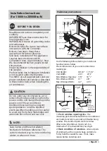
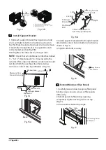
Check your storm windows
-- if your storm
window frame does not allow the clearance
required, correct by adding a piece of wood
as shown in Fig.E,or by removing storm window
while room air conditioner is being installed.
4 .
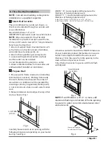
Check for anything that could block
airflow
- check area outside of window for things
such as shrubs, trees, or awnings. Inside, be sure
furniture, drapes, or blinds will not stop proper
airflow.
5.
Check the available electrical service
- Power
supply must be the same as that shown on the
unit serial nameplate. Power cord is 48 inches
long. Be sure you have an outlet near.
6.
Carefully unpack air conditioner
- Remove all
packing material. Protect floor or carpet from
damage. Two people should be used to move
and install unit.
Tools Required
A large flat blade screwdriver; Tape measure;
Adjustable wrench or pliers; Pencil; Level Socket
wrenches; Phillips Screwdriver.
Hardware(Packed with the unit)
1
Front Grille
Front Panel
shipping
screws
Remove Air Conditioner from Cabinet
A. Window Mounting
NOTE:
Remove any packaging material from
cabinet exterior.
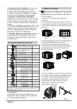
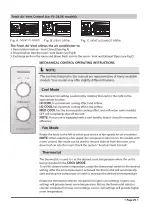
1. Pull down front grille and remove filter.
(See Fig.1).
2. Lift front grille upwards and place to one side.
3. Locate the four front screws and remove. These
screws will be needed to re-install the front panel
(see Fig.2).
4. Push metal cabinet side to release plastic tabs
on each side of front panel (see Fig.3).
5. Gently lift front panel off unit(see Fig.3A).
6. Disconnect the connector plug of the display
panel from the unit and place front panel to
one side(see Fig.4).
7. Remove shipping screws from top of unit and
also on the side by the base if installed(see Fig.5).
8. Hold the cabinet while pulling on the base
pan handle, and carefully remove the unit.
9. Add two foam inserts to holes in top of
cabinet where shipping screws were
removed from (see Fig .6)
Fig.1
Fig.2
Fig.3
Fig.3A
Fig.4
Fig.5
Fig.6
Summary of Contents for KAW05M1AWT
Page 1: ...KAW05M1AWT KAW05R1AWT KAW06R1AWT KAW08R1AWT KAW10R1AWT KAW12R1AWT KAW15R1AWT ...
Page 7: ......
Page 13: ......
Page 17: ......
Page 18: ......
Page 27: ......
Page 30: ......
Page 36: ......
Page 37: ...RG15A B E ...
Page 38: ......
Page 39: ......
Page 40: ......
Page 41: ......
Page 42: ......
Page 43: ......
Page 44: ......

