background image

Arduino® Nano 33 IoT 

13 / 18

Arduino® Nano 33 IoT / Rev. 01 - 06/12/2021

Pin Function Type

Description

27

D9/PWM

Digital

GPIO; can be used as PWM

28

D10/PWM Digital

GPIO; can be used as PWM

29

D11/MOSI Digital

SPI MOSI; can be used as GPIO

30

D12/MISO Digital

SPI MISO; can be used as GPIO

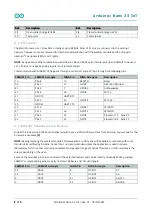
5.3 Debug

On the bottom side of the board, under the communication module, debug signals are arranged as 3x2 test pads
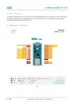
with 100 mil pitch. Pin 1 is depicted in Figure 3 – Connector Positions

Pin

Function

Type

Description

1

+3V3

Power Out

Internally generated power output to be used as voltage reference

2

SWD

Digital

SAMD11 Single Wire Debug Data

3

SWCLK

Digital In

SAMD11 Single Wire Debug Clock

4

UPDI

Digital

ATMega4809 update interface

5

GND

Power

Power Ground

6

RST

Digital In

Active low reset input

6 Mechanical Information

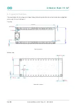
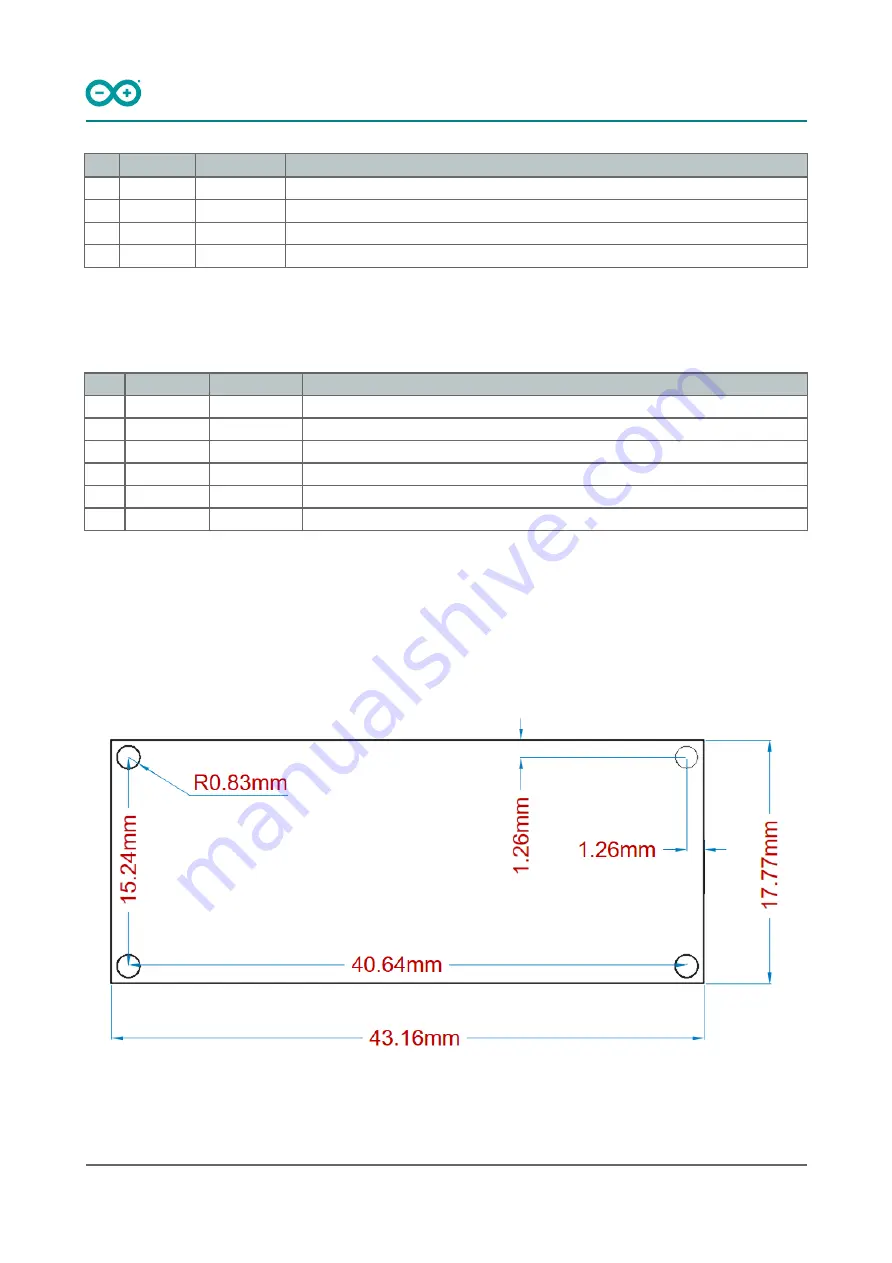
6.1 Board Outline and Mounting Holes

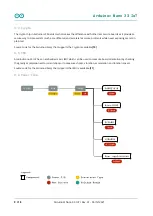
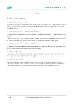
The board measures are mixed between metric and imperial. Imperial measures are used to maintain a 100 mil
pitch grid between pin rows to allow them to fit a breadboard whereas board length is Metric.

Layout

Summary of Contents for ABX00027

Page 1: ...g a Cortex M0 SAMD21 processor a WiFi BT module based on ESP32 a crypto chip which can securely store certificates and pre shared keys and a 6 axis IMU The module can either be mounted as a DIP compon...

Page 2: ...ipherals 12 channel DMA 12 channel event system 5x 16 bit Timer Counter 3x 24 bit timer counter with extended functions 32 bit RTC Watchdog Time CRC 32 generator Full speed Host Device USB with 8 end...

Page 3: ...3 Mbit s 88 dBm sensitivity Bluetooth Low Energy Bluetooth 4 2 dual mode 2 4GHz 40 channels 6 dBm output power 9 dBm EIRP 88 dBm sensitivity Up to 1 Mbit MPM3610 DC DC Regulates input voltage from up...

Page 4: ...Nano 33 IoT 4 18 Arduino Nano 33 IoT Rev 01 06 12 2021 LSM6DSL 6 axis IMU Always on 3D accelerometer and 3D gyroscope Smart FIFO up to 4 KByte based 2 4 8 16 g full scale 125 250 500 1000 2000 dps ful...

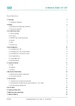
Page 5: ...IMU 3 6 Power Tree 4 Board Operation 4 1 Getting started IDE 4 2 Getting started Arduino Web Editor 4 3 Getting started Arduino IoT Cloud 4 4 Sample Sketches 4 5 Online Resources 4 6 Board Recovery 5...

Page 6: ...erature humidity etc directly to your phone Air quality monitor Bad air quality may have serious effects on your health By assembling the Nano 33 IoT with a sensor and monitor you can make sure that t...

Page 7: ...Overview 3 1 Board topology Board topology top Ref Description Ref Description U1 ATSAMD21G18A Controller U3 LSM6DSOXTR IMU Sensor U2 NINA W102 00B WiFi BLE Module U4 ATECC608A MAHDA T Crypto Chip J1...

Page 8: ...wledge 23 PA14 28 GPIO5 SPI CS 21 GPIO19 UART RTS 24 PA15 29 GPIO18 SPI CLK 20 GPIO22 UART CTS 22 PA13 1 GPIO21 SPI MISO 21 PA12 36 GPIO12 SPI MOSI 31 PA22 23 GPIO3 Processor TX Nina RX 32 PA23 22 GPI...

Page 9: ...es secure protocols while never exposing secrets in plain text Source code for the Arduino Library that supports the Crypto is available 10 3 5 IMU Arduino Nano 33 IoT has an embedded 6 axis IMU which...

Page 10: ...d support for all boards Follow 3 to start coding on the browser and upload your sketches onto your board 4 3 Getting started Arduino IoT Cloud All Arduino IoT enabled products are supported on Arduin...

Page 11: ...duino boards have a built in bootloader which allows flashing the board via USB In case a sketch locks up the processor and the board is not reachable anymore via USB it is possible to enter bootloade...

Page 12: ...ed as GPIO 4 A0 DAC0 Analog ADC in DAC out can be used as GPIO 5 A1 Analog ADC in can be used as GPIO 6 A2 Analog ADC in can be used as GPIO 7 A3 Analog ADC in can be used as GPIO 8 A4 SDA Analog ADC...

Page 13: ...depicted in Figure 3 Connector Positions Pin Function Type Description 1 3V3 Power Out Internally generated power output to be used as voltage reference 2 SWD Digital SAMD11 Single Wire Debug Data 3 S...

Page 14: ...Rev 01 06 12 2021 6 2 Connector Positions The view below is from top however it shows Debug connector pads which are on the bottom side Highlighted pins are pin 1 for each connector Top view Top side...

Page 15: ...B 1000 Poly Brominated Diphenyl ethers PBDE 1000 Bis 2 Ethylhexyl phthalate DEHP 1000 Benzyl butyl phthalate BBP 1000 Dibutyl phthalate DBP 1000 Diisobutyl phthalate DIBP 1000 Exemptions No exemptions...

Page 16: ...on FCC RF Radiation Exposure Statement 1 This Transmitter must not be co located or operating in conjunction with any other antenna or transmitter 2 This equipment complies with RF radiation exposure...

Page 17: ...uino IDE Cloud https create arduino cc editor Cloud IDE Getting Started https create arduino cc projecthub Arduino_Genuino getting started with arduino web editor 4b3e4a Forum http forum arduino cc SA...

Page 18: ...Arduino Nano 33 IoT 18 18 Arduino Nano 33 IoT Rev 01 06 12 2021 11 Revision History Date Revision Changes 04 15 2021 1 General datasheet updates...

Reviews: