background image

Arecont Vision MegaView

®

 2 Installation Manual 


Page | 12       support@arecontvision.com 

CAUTION: If the software does not find a 
camera, the software utility may be blocked by 
the anti-virus or Windows® firewall. Before 
turning them off, please consult your IT 
manager.  

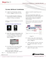
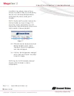
NOTE : Double click the camera model on the 
Camera Installer as shown in Image 17 to 
access the camera web interface. See “AV 
Camera Web Page User Manual” (found on the 
CD) for details on the web interface.  


Image 17 


29.  When all cameras are discovered and 

display “Installed, online”, select 
“Save/Exit.” The AV100 application 
main menu will appear.  

 
30.  From the “AV100 Application Manager” 

menu, select “Run” next to “Live video” 
to view live images.   


NOTE: See the “AV100 Installation Manual” 
(found on CD) for details on camera 
configurations. 


Summary of Contents for AV10225PMIR

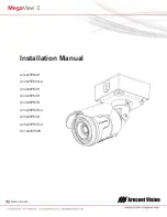
Page 1: ...Installation Manual AV2225PMIR AV2225PMIR A AV2226PMIR AV3225PMIR AV3226PMIR AV3226PMIR A AV5225PMIR AV5225PMIR A AV10225PMIR ...

Page 2: ...egaView 2 Camera 5 Replacing the IR LED board 10 Camera Software Installation 11 Electrical Box Adapter SV EBA Installation Instructions Sold Separately 13 Pole Mount Adapter MD PMA Installation Instructions Sold Separately 14 Corner Mount Adapter MD CRMA Installation Instructions Sold Separately 15 LED Indicators Camera Signal 16 Support 17 Mounting Template 18 ...

Page 3: ...ack of four vision com ontents Camera P on MegaView adapter mplate for Ju mplate for M 00 software ey 4 wood scr 4 machine Image 1 A ackage w 2 Camera unction box MegaView 2 and user ma rews and fou screws 8 D Arecont a adapter 2 Camera anuals licen ur 4 dry wa 32 Philli E t Vision Me nse key requ all anchors ips Pan Hea B F G egaView uired for reco ad C G H 2 Installati ording I ion Manua al ...

Page 4: ...misuse abuse improper storage testing or connection or unauthorized repair or iv is no longer covered under the Warranty Period ARECONT VISION MAKE NO WARRANTIES OR CONDITIONS EXPRESS IMPLIED STATUTORY OR OTHERWISE OTHER THAN THE EXPRESS LIMITED WARRANTIES MADE BY ARECONT VISION ABOVE AND ARECONT VISION HEREBY SPECIFICALLY DISCLAIMS ALL OTHER EXPRESS STATUTORY AND IMPLIED WARRANTIES AND CONDITIONS...

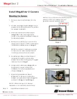
Page 5: ...e nting provisi allation Junction Box he wall using ptional hardw rface duit plug on nect NPT apter shown on or water p water leakag junction box ble and othe gh the Junc nect to Mega n Image 8 bber plug Im sure a wate utdoor applic 3 cable and at mera to Jun ovided screw ge 3 1 and I age from im vered by the 2 Came are from the Image 1 C ons for junc x Adapter g drywall ware suitable Junction bo ...

Page 6: ...otation Im NOTE 3 Me solution to p fan Fan is a NOTE 4 To or 24VAC p power with p NOTE 5 On have female Digital I Audio Out dio In Power egaView acket screw mper resistan acket with 3 in any locatio dy rotation 9 mage 7 Ima egaView 2 i power the ca always on o use the ext power on cam pigtail cable nly MegaVie e 3 5mm aud Image 8 360 n 2 Installati ws are all sec nt axes enable on including 90 til...

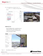
Page 7: ...nd Remote Zoom NOTE MegaView 2 camera operating temperature is 40 C 40 F to 50 C 122 F however motorized lens operating temperature is 20 C 4 F to 50 C 122 F 10 To adjust focus or zoom open the camera web interface and click the Focus tab as shown in image 9 11 To manually adjust zoom click the 20 5 1 20 5 1 buttons to zoom in and out adjusting the field of view NOTE 1 20 zooms in 20x further than...

Page 8: ... com 16 To manually focus click the 20 5 1 20 5 1 buttons to fine tune the focus Image 9 Adjusting P Iris Note If Enable P Iris is unchecked the iris will be fully open to the maximum It may result in less sharpness and artificial color under strong light condition Image 9 1 ...

Page 9: ...ect a mono analog microphone to MICIN Microphone In and connect an active speaker with a built in amplifier to LOUT Line Out via the in line jack as shown in Image 8 if needed 18 Enable audio on the MegaView 2 Camera Web interface as shown in Image 10 NOTE Audio only works in H 264 RTP UDP streaming Image 10 ...

Page 10: ...hillips screw d Image 12 eplace IR LE ce new IR L R LED board tvision com he IR L ng Image 1 wdriver to re ED board un LED board I d part numbe Image 11 ED boa 1 emove IR LE nplug cable a mage 12 1 er M000094 Arecont ard ED and 4 34 t Vision Me egaView Imag Imag 2 Installati ge 12 ge 12 1 ion Manua al ...

Page 11: ...mage 15 25 Click Mode tab to select desired install mode on the Arecont Vision Camera Installer as shown in Image 16 NOTE 1 Basic Mode software will automatically discover and change assign IP address to match PC subnet if they are not locked NOTE 2 Advanced Mode software will automatically discover but allow manual update of the IP address See AV100 Installation Manual found on the CD for details...

Page 12: ... model on the Camera Installer as shown in Image 17 to access the camera web interface See AV Camera Web Page User Manual found on the CD for details on the web interface Image 17 29 When all cameras are discovered and display Installed online select Save Exit The AV100 application main menu will appear 30 From the AV100 Application Manager menu select Run next to Live video to view live images NO...

Page 13: ...the wall m ctrical box ad ch adapter t ox Ada rately x Adapter 4 machine 8 eeded ctrical box s uble gang b xes shown in ctrical box a he box mount brack dapter to electrical b Me Bra apter S screws such as sing ox or squar n Image 18 1 dapter and et to the box egaView 2 acket holes B SV EBA gle re 1 4 A Instal Ima Imag I I lation I age 18 1 Si ge 18 2 Dou Image 18 3 Image 18 4 Instruc ngle gang b ...

Page 14: ...ect unction Box A 1 on or water p water leakag junction box C er MD screws adapter apter steel m the box Mount Adapte Box Adapte g on Junction t NPT Adapter sho pipe seal tap ge between x adapter D E Arecont PMA I er er n wn pe t Vision Me nstalla 5 Run nece Adap pigta 6 Attac Moun 7 Use attac pole screw 8 To a refer need Imag egaView tion Ins Ethernet Ca essary throu pter and con ail cable ch Meg...

Page 15: ... connect unction Box A 1 on or water p water leakag junction box B C pter M screws d screws and adapter Adapter and r Mount age 23 Box Adapte g on Junction t NPT Adapter sho pipe seal tap ge between x adapter D MD CRM d er n wn pe 5 6 7 8 MA Inst 5 Run Ethe necessa Adapter cable 6 Attach M Mount A 7 Using th hardware Adapter shown in 8 To adjus referenc needed Im tallatio ernet Cable ary through a...

Page 16: ...ra Signal NOTE To see the LED indicators open the plug on the camera body as shown in Image 25 Image 25 LED Status Description Yellow Flashing Link has been established Solid Normal Operation None No connection Green Flashing Camera has been accessed Normal operation Solid N A None No Connection Plug ...

Page 17: ... the camera webpage Upgrade to the latest firmware by visiting ArecontVision com Isolate the camera on a dedicated network and test with AV100 or AV200 Swap the troubled camera with a known good camera to see if the problem follows the camera or stays at the location 3 Contact Arecont Vision Technical Support one of three ways 1 Online Portal Support ArecontVision com 2 Phone 1 818 937 0700 option...

Page 18: ...Arecont Vision MegaView 2 Installation Manual Page 18 support arecontvision com Mounting Template Junction Box Adapter Mounting Template ...

Reviews: