background image

 Arecont Vision SurroundVideo

® 

WDR Camera Installation Manual 

8 | 

P a g e


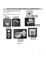
Since AV12186DN/AV12366DN cameras utilize the 
same housing as MegaDome®, it also shares the 
same accessories. 

Please check MegaDome installation manual for 
more detail.  


`               


                                                    Image 16 


MD-CMT 

MD-CAP 

MD-WMT2 

MD-CRMA 

MD-PMA 

SV-EBA 

SV-JBA FOR 

MD-WMT2 

Summary of Contents for AV12186DN SurroundVideo

Page 1: ...Arecont Vision SurroundVideo WDR Camera Installation Manual 1 P a g e...

Page 2: ...be used in wood Not included but needed 2 Phillips head screw driver Image 1 How to Mount the Camera 1 Remove camera and hardware from the box 2 Using the Mounting template prepare the mounting provis...

Page 3: ...l government where the camera is installed and no bare wires are exposed 6 Align the holes in the camera with the prepared holes on the mounting surface Attach the camera to the mounting surface with...

Page 4: ...ab gimbal by the brackets not the ball to avoid direct contact with lenses not to damage them or leave fingerprints on glass 11 To focus each of four lenses remove the lens cap and focus the lens as s...

Page 5: ...e Default setting software will automatically discover but allow manual update of the IP address See AV100 Installation Manual found on the CD for details on Advanced Mode NOTE 2 Basic Mode software w...

Page 6: ...the camera web interface See AV Camera Web Page User Manual found on the CD for details on the web interface Image 12 21 When all cameras appear select Save Exit The AV100 application will appear 22...

Page 7: ...E The default setting for the Exposure Reference Channel is Auto which means that each channel is automatically adjusted to provide the best WDR scene This may cause variations from image to image how...

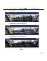
Page 8: ...recont Vision SurroundVideo WDR Camera Installation Manual 8 P a g e Exposure Reference Channel set as Auto Exposure Reference Channel set as Channel 1 Exposure Reference Channel as Channel 2 Image 15...

Page 9: ...Manual 8 P a g e Since AV12186DN AV12366DN cameras utilize the same housing as MegaDome it also shares the same accessories Please check MegaDome installation manual for more detail Image 16 MD CMT MD...

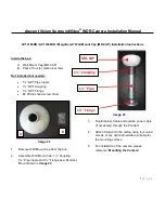
Page 10: ...move Pendant Mount and hardware from the box Image 18 Image 19 2 Using Mounting template prepare the mounting provisions for camera installation 3 Place small gasket onto pendant dome as shown in imag...

Page 11: ...themselves can be used in wood Not included but needed 2 Phillips head screw driver Image 20 1 Remove Wall Mount and hardware from the box Image 21 2 Using the mounting template prepare the mounting...

Page 12: ...e 2 Phillips head screw driver Image 22 1 Remove Wall Mount Cap from the box 2 Assemble Wall Mount Cap 1 Coupling 1 Pipe nipple and 1 Flange as a Pendant Mount shown in image 23 Image 23 3 Run Etherne...

Page 13: ...crews by themselves can be used in wood E Mounting template Not included but needed 2 Phillips head screwdriver Wall Mount MD WMT NPT Conduit if necessary Image 24 1 Remove junction box adapter and ha...

Page 14: ...g and hardware from the box 2 Attach Dome to Flush Mount Adapter as shown in Image 27 Please reference Mounting the Camera if needed 3 Using the Mounting template cut a hole in surface for mounting 4...

Page 15: ...Electrical Box Adapter Pack of four 4 machine screws 8 32 7 16 Image 29 Not included but needed Common electrical box such as single gang box double gang box or square electrical boxes shown in Image...

Page 16: ...side the box B Electrical Box Adapter C Pack of four 4 machine screws M4 10mm Not included but needed 2 Phillips head screw driver Common Electrical Box such as single gang box double gang box or squa...

Page 17: ...Straps and hardware from the box 2 Install Compress Fittings to Pole Mount Adapter as shown in Image 35 3 Attach MegaDome Wall Mount Adapter to Pole Mount Adapter as shown in Image 36 4 Run Ethernet...

Page 18: ...Image 37 1 Remove Corner Mount Adapter Compress Fitting and hardware from the box 2 Install Compress Fittings to Corner Mount Adapter as shown in Image 38 3 Attach Wall Mount Adapter to Corner Mount...

Page 19: ...e not to damage wire insulation Image 38 Table 1 Electrical Characteristics Min Max Input voltage V ON 2 9 6 3 measured between and terminals OFF 0 1 3 Output current mA ON 50 measured between and ter...

Page 20: ...Arecont Vision SurroundVideo WDR Camera Installation Manual 19 P a g e...

Reviews: