background image

Arecont Vision MegaBall™ Installation Manual 

0 | P a g e


Summary of Contents for MegaBall

Page 1: ...Arecont Vision MegaBall Installation Manual 0 P a g e ...

Page 2: ...te prepare the mounting surface for camera installation 3 Plug the Ethernet cable into the MegaBall PoE female RJ45 connector Image 2 NOTE If the camera will be powered via PoE please skip to step 5 Image 2 4 If the camera will be powered by an AC or DC power supply connect external power with pigtail cable connector NOTE 1 Ensure that the polarity of the DC input on the camera matches the way tha...

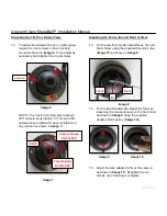
Page 3: ... bracket ring may result in scratches on the bracket joint Incorrect installation practices are not covered under warranty 7 For the vari focal model adjust the focus iris and field of view using the provided Security L Key Image 1F as shown in Image 5 Adjusting the Focus Iris and Field of View Image 5 8 For the fixed focal model adjust the focus by loosening the two set screws on the front shell ...

Page 4: ...llips head screwdriver Not included but needed Image 1 Mounting the Camera 1 Remove the camera and hardware from the box 2 Using the mounting template prepare the mounting surface for camera installation 3 Plug Ethernet cable into the MegaBall PoE female RJ45 connector Image 2 NOTE If the camera will be powered via PoE please skip to step 5 Image 2 4 If the camera will be powered by an AC or DC po...

Page 5: ...ate cut a hole in the surface for mounting In ceiling Mount Installation Optional 8 Insert the in ceiling mount camera into the hole 9 Tighten the lever screws until the flush mount is snug as shown in Image 5 The Support Arm will ride down the screw to compress the mounting surface NOTE Do not over torque the lever screws Image 5 10 Align the holes in the surface mount with the prepared holes on ...

Page 6: ...y location as shown in Image 7 Image 7 13 For the vari focal model adjust focus iris and field of view using the provided Security L Key Image 1F as shown in Image 8 Adjusting the Focus Iris and Field of View Image 8 14 For the fixed focal model adjust the focus by loosening the two set screws on the front shell as shown in Image 9 using the supplied double sided hex key Image 1G Image 9 Image 10 ...

Page 7: ...onnecting Digital I O NOTE Table 1 shows the electrical characteristics and Table 2 shows cable color for digital I O Electrical Characteristics Min Max Camera Input voltage V measured between and terminals ON 2 9 6 3 IR DN Versions OFF 0 1 3 Output current mA measured between and terminals Applied Voltage Rage 0 80V ON 50 DN version Only OFF 0 1 Table 1 NOTE Both the input and the output are elec...

Page 8: ...ed Mode software will automatically discover but allow manual update of the IP address See AV100 Installation Manual found on the CD for details on Advanced Mode NOTE3 User can verify camera model number and FW version of all cameras as shown in Image 16 Image 16 25 For basic mode select Install Cameras on the Arecont Vision Camera Installer as shown in Image 16 26 Confirm that all the cameras con...

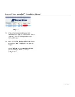
Page 9: ...covered and installed and display Installed online select Save Exit The AV100 application main menu will appear 29 From the AV100 Application Manager menu select Run next to Live video to view live images NOTE See the AV100 Installation Manual found on CD for details on camera configurations ...

Page 10: ...Arecont Vision MegaBall Installation Manual 1 P a g e R ...

Reviews: