Arecont Vision MegaBall™ Installation Manual
6 | P a g e
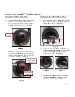
16. Remove the O-ring (
Image 1C
) from the bezel
by pushing on the 4 drift pins on the back of
bezel shown in
Image 11
.
Dome Cover (Bubble) Installation (Optional):
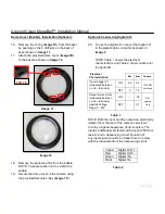
17. Attach the provided dome cover (
Image 1D
)
to the bezel as shown in
Image 12.
Image 11
Image 12
18. Remove the protective film from the bubble.
NOTE: Take precaution not to scratch the
bubble.
19. Secure the dome cover to the camera using
the provided Security L-Key (
Image 1F.
)
20. To use the digital I/O, connect the digital I/O
to the pigtail cable connector as shown in
Image 2
.
Optional: Connecting Digital I/O:
NOTE: Table 1 shows the electrical
characteristics and Table 2 shows cable color
for digital I/O.
Electrical
Characteristics:
Min
Max
Camera
Input voltage (V)
(measured between
+ and – terminals)
ON
2.9
6.3
IR & DN
Versions
OFF
0
1.3
Output current (mA)
(measured between
+ and – terminals)
Applied Voltage
Rage: 0 - 80V
ON
-
50
DN
version
Only
OFF
-
0.1
Table 1
NOTE: Both the input and the output are electrically
isolated from the rest of the camera’s electrical
circuitry via general-purpose photo couplers. The
input is additionally protected with a serial 250 Ohm
resistor and a debouncing circuit. Duration of
any input signal should be at least 5ms to comply
with the requirements of the debouncing circuit.
Yellow
Digital OUT +
Red
Digital OUT –
Green
Digital IN +
Black
Digital IN -
Table 2
Drift Pin


