Installation DXC5K/EN
IN/A22
DXC 5000
Page 13/34
Ethernet port can be connected via Ethernet 10-Base-T interface. Pin definition is listed in
Table 2-6.
Pin Number
Signal
Description
1 TPTX+
TP
Driver
Output
2 TPTX-
3
TPRX+
TP Receive Input
6 TPRX-
TABLE 5: ETHERNET PORT
Pin Number
Signal
1 R
TIP
2 R
RING
4 T
TIP
5 T
RING
7
Chassis Ground/ Unassigned
8
Chassis Ground/ Unassigned
TABLE 6: E1 BNC/ RJ 45 AND T1 PORT
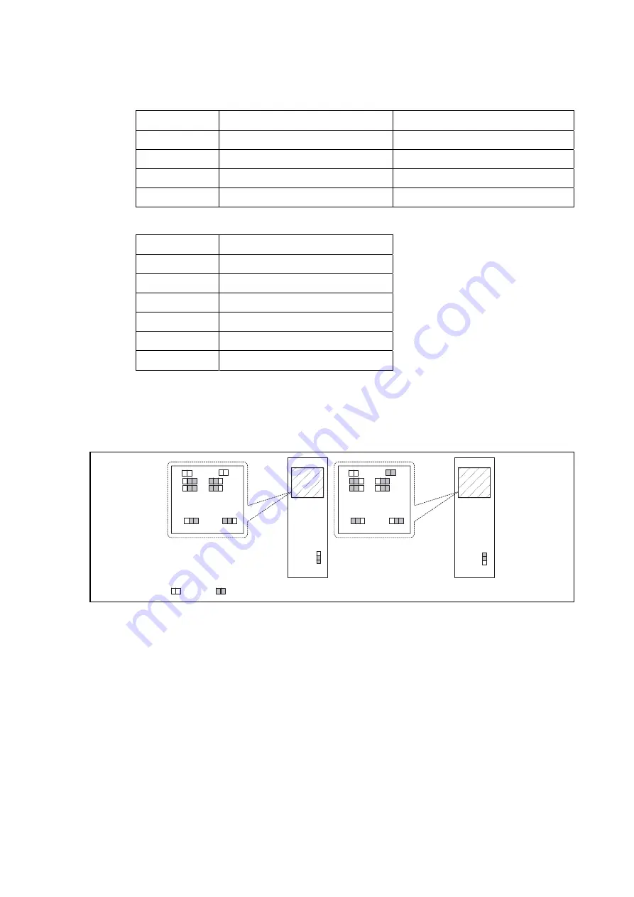
Normally the choice for the E1 connector, balanced 120 ohm or unbalanced BNC 75 ohm, is
installed at the factory according to the customer order. Users can change this choice by
opening the case and changing the jumper pins as indicated in the Table 2-8.
D0334ENa
120 ohm
E1 Card
JUM5
JUM6
JUM1
JUM2
JUM4
JUM3
JUM5
JUM6
JUM1
JUM2
JUM4
JUM3
75 ohm
JU
M8
JU
M8
JUM9
JUM9
JUM10
JUM10
OPEN, OFF
CLOSE, ON
FIGURE 10: JUMPER LOCATIONS FOR E1 CARD
NOTE 1:
For 75 ohm E1 card, jumper 9 can be OPEN or ON. If the jumper 9 is
OPEN, BNC connector is set to Unassigned. If the jumper 9 is ON,
BNC connector is set to Chassis Ground.
NOTE 2 :
For 120 ohm E1 card, jumper 9 can be OPEN or ON. If the jumper 9 is
OPEN, port 7 and port 8 of BNC connector is set to Unassigned. If the
jumper 9 is ON, port 7 and port 8 of BNC connector is set to Chassis
Ground.
NOTE 3 :
BNC is open if jumper 10 is opened, BNC is grounded if jumper 10 is
closed.
NOTE
4:
When BNC connector is selected, the user has the option of
grounding the received BNC shield by installing a jumper clip on the
jumper location. This is usually not necessary, but if you have any
noise on your device it can often be filtered out by using this
grounding process.


