Installation DXC5K/EN
IN/A22
DXC 5000
Page 7/34
3. ELECTRICAL
INSTALLATION
3.1 Front
Views
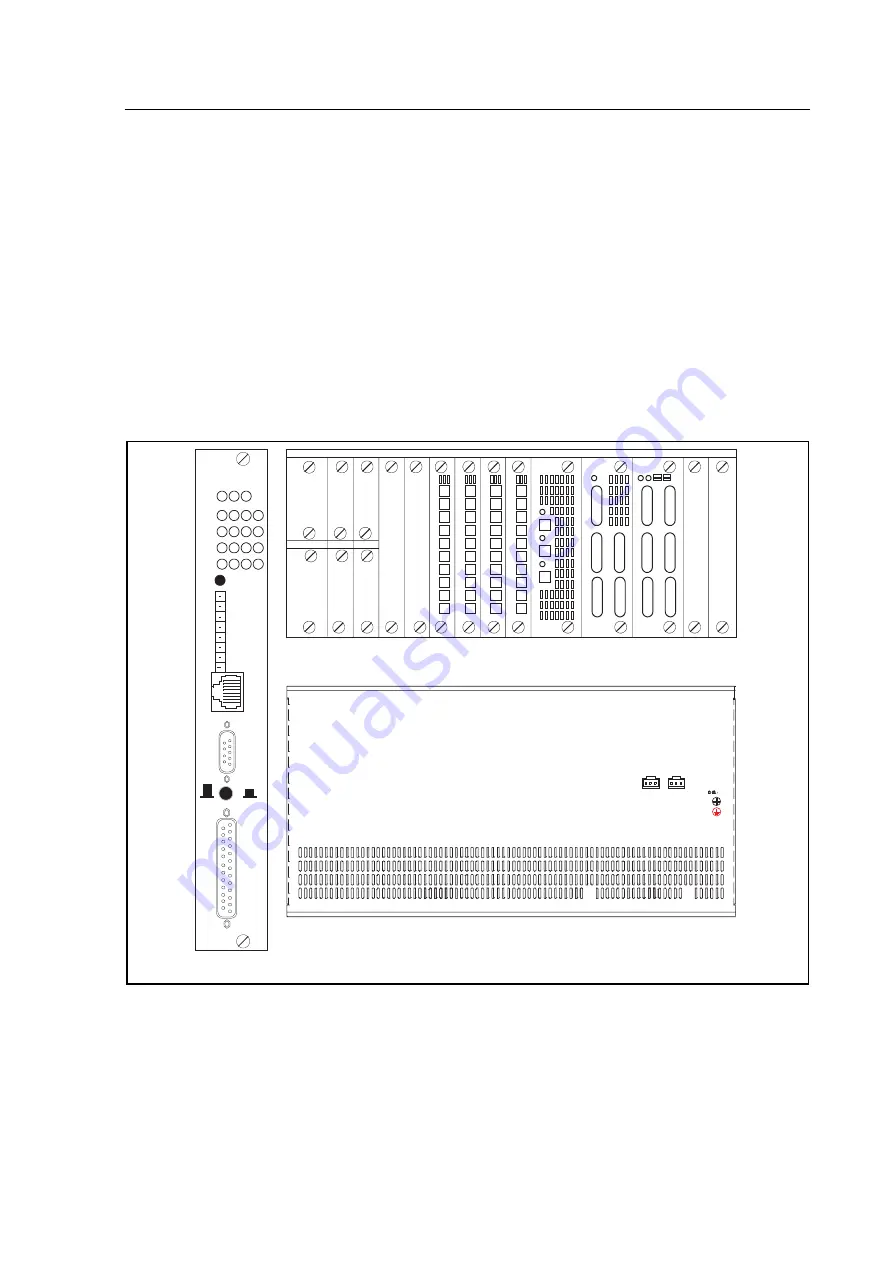
Central office -48 Vdc power is wired to terminal blocks in the front of the DXC 5000, shown
in Figure 2-1. Central office alarm system is wired to the Alarm Relay terminal blocks. For
connection to the CONSOLE/SLIP (button down/ button up) connector for maintenance and
administration, a CONSOLE/SLIP port with DB9 connector is located on the front panel, see
also Figure 2-1. The RJ45 connector is for an Ethernet connection. For direct modem or VT-
100 terminal connection, use a null modem cable to connect the CONSOLE/SLIP port on the
front panel.
When DXC 5000 is plugged with two CPU cards, both of these two CPU cards can be
primary (master) or redundant (slave) which only depends on which CPU card completes
boot up first after powering on the main unit. User can tell which CPU card is primary or
redundant from the status of CPU card's ACTIVE led. If ACTIVE led is flashing green, the
CPU card is primary. When one CPU fails, the other becomes master and remains master
even when the failed is replaced.
D0328ENb
CONSOLE
SLIP
CO
NS
O
L
E
/S
L
IP
9600,
N
,8
,1
ET
H
E
R
N
ET
LC
D
IN
TE
R
F
A
C
E
AL
AR
M
AC
T
IV
E
PO
W
E
R
EXT.
CLOCK
TIP
RING
NC
NO
COM
NC
NO
COM
MINOR
ALARM
MAJOR
ALARM
SYNC/
TEST
LOF
BPV
RAI/AIS
ACO
A B C D
CPU
1
11
10
9
8
7
6
5
4
3
2
12
CPU-1
CPU-2
POWER
E1/T1 E1/T1
E1/T1
C
P
U
1
E1/T1
C
P
U
2
Main Access DCS-Mux Shelf - Front Side
Main Access DCS-Mux Shelf - Rear Side
E1/T1(C)E1/T1(D)
E1/T1(A)
E1/T1(B)
FAN TRAY
FAN TRAY
GND
-V+V ALIM
DC 48V
-V+V ALIM
DC 48V
FIGURE 1: PANEL VIEWS - MAIN SHELF AND CPU
When these plug-in modules, two CPU cards, four mini Quad E1 cards, ten G.shdsl cards,
and one 100W UM5813 power module, are plugged into a DXC 5000, one more 100W
UM5813 power module should be added to plug into the DXC 5000.


