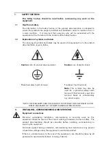
Voltage and current connections should be made using insulated crimp terminations
to ensure that terminal block insulation requirements are maintained for safety. To
ensure that wires are correctly terminated, the correct crimp terminal and tool for the
wire size should be used.
Before energising the equipment it must be earthed using the protective earth
terminal, or the appropriate termination of the supply plug in the case of plug
connected equipment. Omitting or disconnecting the equipment earth may cause a
safety hazard.
The recommended minimum earth wire size is 2.5mm
2,
unless otherwise stated in the
technical data section of the product documentation.
Before energising the equipment, the following should be checked:
−
Voltage rating and polarity;
−
CT circuit rating and integrity of connections;
−
Protective fuse rating;
−
Integrity of earth connection (where applicable)
−
Remove front plate plastic film protection
−
Remove insulating strip from battery compartment
3.
EQUIPMENT OPERATING CONDITIONS
The equipment should be operated within the specified electrical and environmental
limits.
3.1
Current transformer circuits
Do not open the secondary circuit of a live CT since the high level voltage produced
may be lethal to personnel and could damage insulation.
3.2 External
resistors
Where external resistors are fitted to relays, these may present a risk of electric shock
or burns, if touched.
3.3 Battery
replacement
Where internal batteries are fitted they should be replaced with the recommended
type and be installed with the correct polarity, to avoid possible damage to the
equipment.
3.4
Insulation and dielectric strength testing
Insulation testing may leave capacitors charged up to a hazardous voltage. At the
end of each part of the test, the voltage should be gradually reduced to zero, to
discharge capacitors, before the test leads are disconnected.
3.5
Insertion of modules and pcb cards
These must not be inserted into or withdrawn from equipment whist it is energised
since this may result in damage.
Summary of Contents for MVAJ05
Page 1: ...Types MVAJ05 10 20 Tripping and Control Relays Service Manual R8141B...
Page 2: ......
Page 4: ......
Page 8: ......
Page 36: ...Page 34...
Page 39: ......


