Page 30
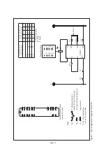
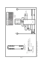
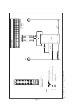
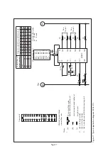
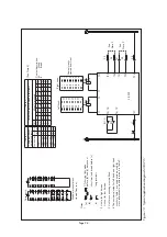
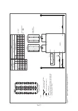
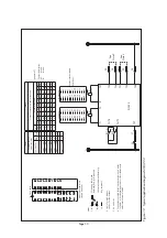
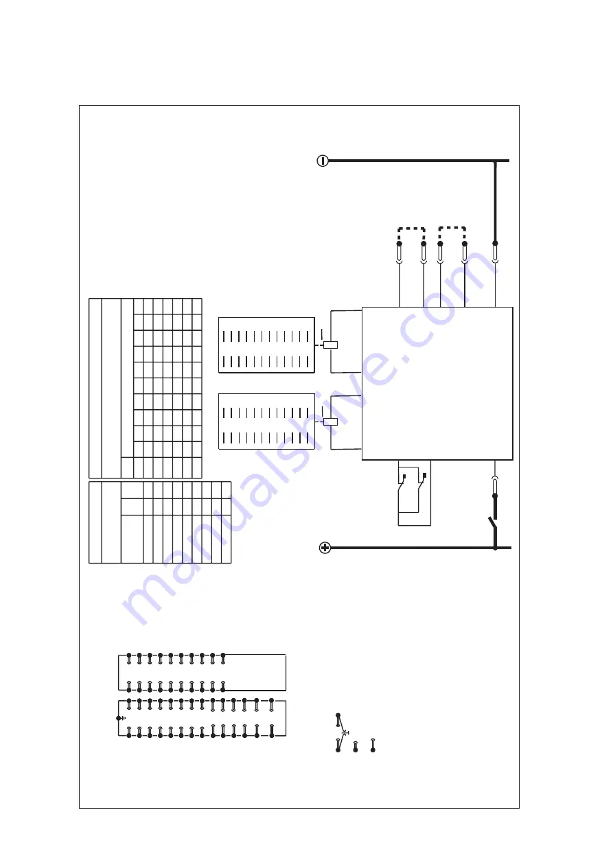
Figure 12: T
ypical application diagram MV
AJ 203
Table 1
Table 2
Combinations of output contacts
Output contacts to module ter
minals
Module ter
minals
Cont. stack
L/h stack
R/h stack
Combination
(see Note 3)
Left hand
Contact description M:
Make
B:
Break
Right hand
1
MMMM
MMMM
M
M
2
B
M
M
M
MB
MM
M
M
3
BBM
M
M
B
B
M
M
M
4
BBBM
M
B
B
B
M
M
5
BBBB
M
B
B
B
B
M
29
31
33
35
1
3
5
7
37
39
41
43
9
11
13
15
45
47
17
19
2
4
30
32
34
36
38
40
6
8
10
12
42
44
14
16
46
48
18
20
L/h
R/h
2 4 6 8 10 12 14 16 18 20
B
1 3 5 7 9 11 13 15 17 19
A
30 32 34 36 38 40 42 44 46 48
B
29 31 33 35 37 39 41 43 45 47
A
Contact stacks viewed from front
20M
-
1
1
18M
2B
2
1
16M
4B
2
2
14M
6B
3
2
12M
8B
3
3
10M
10B
4
3
8M
12B
4
4
6M
14B
5
4
4M
16B
5
5
(OP)
(OP)
RL1 10
RL3 10
Vx
Case ear
th
Module ter
minal block
viewed from rear
Notes
CT shor
ting links make
before (b) and (c) disconnect
(a)
(b)
(c)
long ter
minals
shor
t ter
minals break before (c)
2 Link in for high burden Link out for low burden
3
Do not fit link
4 The numbers quoted for left hand and right hand stacks in T
able 1 are codenumbers used for cross references to
module ter
minals in T
able 2.
1
12
3
4
5
6
7
8
9
10
11
12
13
14
15
16
17
18
19
20
21
22
23
24
25
26
27
28
29
30
31
32
33
34
35
36
37
38
39
40
41
42
43
44
45
46
47
48
23
21
24
22
See
Note 2
See
Note 3
28
27
PR
RL1-A
T4/T9
T3/T8
RL3-A
T27
T22
T24
T21
T23
T28
T20
T7
T2
T1
ZJ0393
Summary of Contents for MVAJ05
Page 1: ...Types MVAJ05 10 20 Tripping and Control Relays Service Manual R8141B...
Page 2: ......
Page 4: ......
Page 8: ......
Page 36: ...Page 34...
Page 39: ......


