2.4.6.2 Step 2 - process
Now measure the respective minimum and maximum value of the detection range.
• To do this, approach the obstacle (Marvin Box) from approx. 35 cm until the raw value is set to a value
smaller than 255 in the display.
• Find the exact point and write the raw value and the measured distance at the ruler.
• Approach the Marvin with the obstacle (Marvin Box) further until the raw value no longer changes in
the display (minimum value).
• Find the exact point and write the raw value and the measured distance at the ruler.
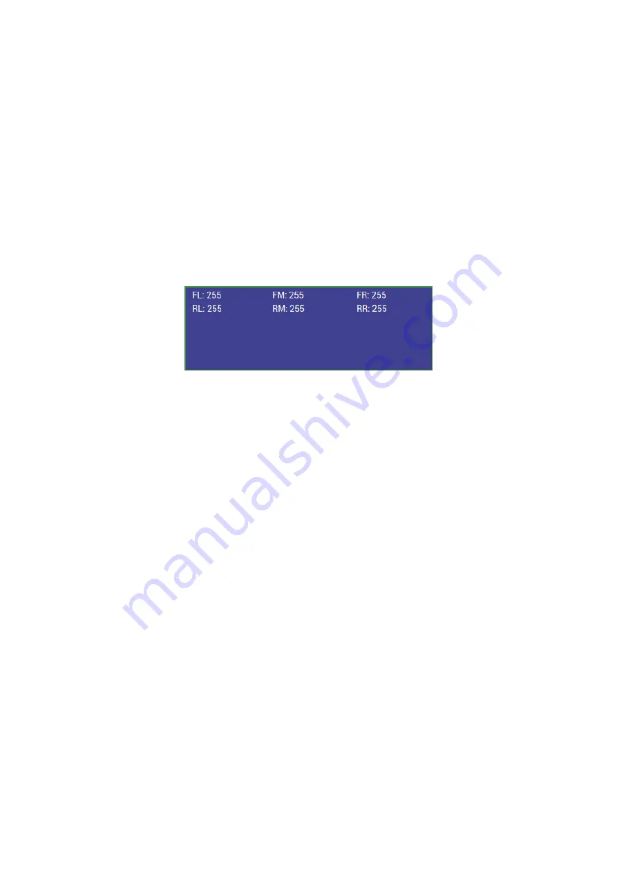
Figure 2.12
iRP auxiliary program data on user screen
Enter the following in the command line:
• cal prox FM 23 135.0 300 170 “Enter”
In this example, the front mid sensor (FM) with the lower raw value of “23” and the measured distance
“13.5” together with the measured distance “300” and the upper raw value of “170” would be used for
calibration.
Hint:
All distances must be entered in “mm”!
After calibration of the Marvin restart the robot (Off and On)!
2.4.6.3 Step 3 - verfication of the calibration
After performing the procedure check the result for the left, right, and center position sensor. For:
• ca. 13 cm must be 0
• ca. 30 cm must be 30
• > 30 cm must be 255 are displayed.
AREXX Engineering & JM³ Engineering
Version: 1.3.1
October 27, 2017
Page: 21


