background image

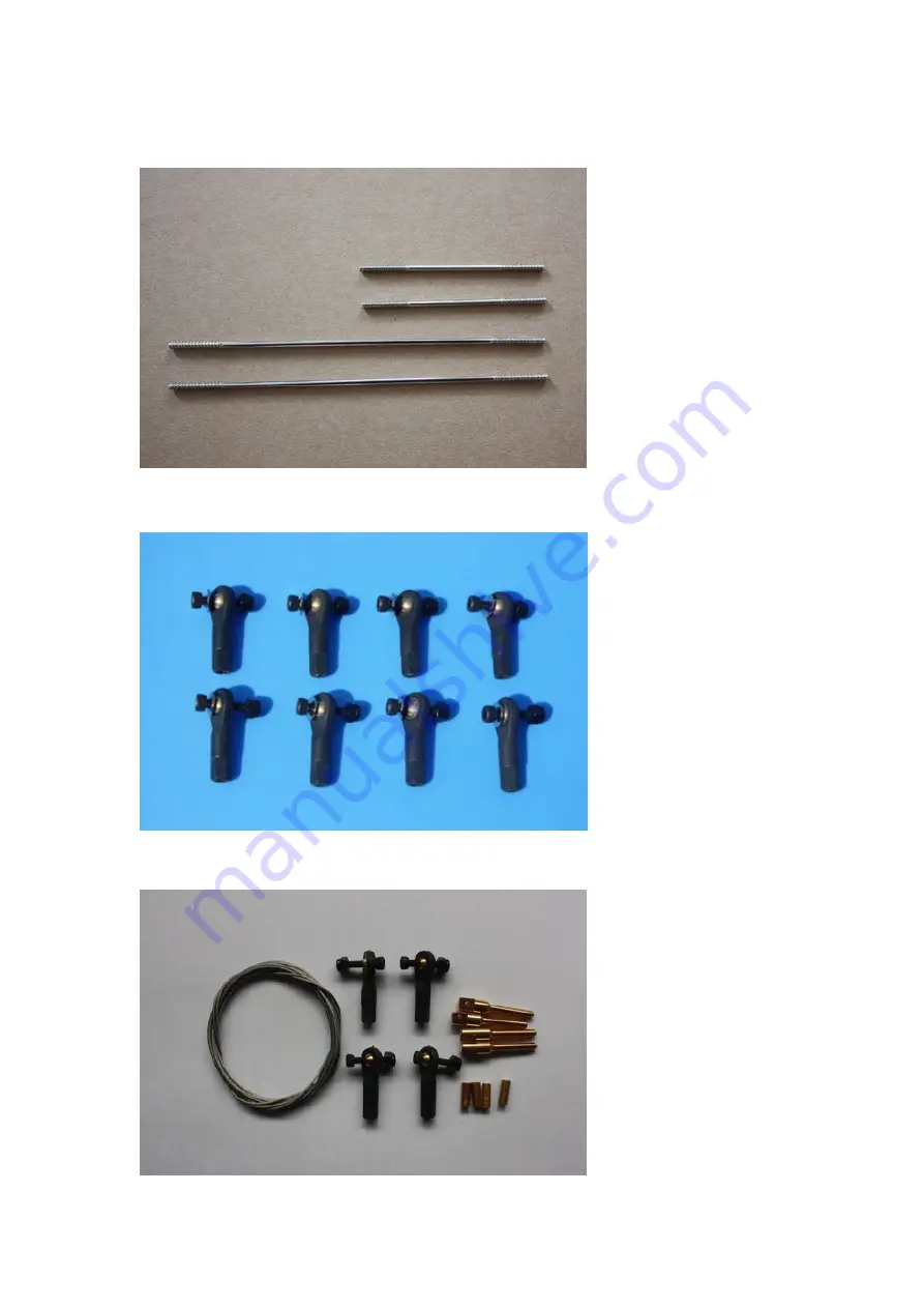
Pushrods: Two 2.5x60mm for aileron. Two 2.5x110mm for elevator (you have option 
to use one or two servos). 


Ball links: 8 for aileron and elevator. 


Pull-pull setup for the rudder. 


Summary of Contents for SBACH300 20CC V2

Page 1: ...ARF MODEL SBACH300 20CC V2 Instruction Manual This plane is designed for electric motor It can also be flied with nitro and gas engine ...

Page 2: ...8 The air exit for the electric set up still needs to be inside the fuselage behind the rudder tray A QUICK WORD ABOUT SAFETY AND RADIO CONTROL FLYING MODELS With radio control aircraft like any hobby or sport there are certain risks The operator of these models is responsible for these risks If misused or abused you may cause serious bodily injury and or damage to property With this in mind you w...

Page 3: ...mers in other areas please contact the sellers you purchased it from SPECIFICATIONS Wing Span 68 1720mm Length 65 1650mm Wing Area 946sq in 61sq dm Flying Weight 8 8 8lbs 3600 4000g Depending on battery size used Engine 70 91 2C 91 110 4C 20 26cc gas Electric Power Hacker A50 16S with 6S 3800 44000mAh 17x8 or 18x8 prop DUSKY XM5060EA 470KV with 6S 3700 4400 mAh 17x8 prop Or other 1500 1800Watt ele...

Page 4: ...Larger aileron and elevator design for excellent 3D aerobatic flying The air exit for the electric set up still needs to be inside the fuselage behind the rudder tray ...

Page 5: ...Include Side Force Generator s SFG Servo extension safety connector clips High performance cap head screws ...

Page 6: ...Flat nylon hinges for better flying strength High quality 2 5mm ball links assemblys ...

Page 7: ...Fiberglass horn assembly High quality durable rubber wheels Two options for landing gear Anodized 6061 Aluminum or Carbon fiber Anodized 6061 Aluminum landing gear ...

Page 8: ...Carbon fiber landing gear Carbon fiber wing tube Two improvements for easier battery access Canopy extended into cowl ...

Page 9: ...Canopy quick release mechanism ...

Page 10: ...It can also be powered by gas engine ...

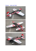
Page 11: ...Scheme A white red black ...

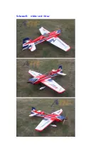
Page 12: ...Scheme B white red blue ...

Page 13: ......

Page 14: ...erons and elevators Appropriate servo arms for the above Servo wire extensions recommends five 12 Two switches with charging jacks for the Rx Two high quality Rx batteries of significant capacity to power your choice of servos One Receiver of your choice Shop Supplies Tools Covering Iron and heat gun Assortment normal hobby tools such as screwdrivers hobby knife drill and drill bits pliers etc Thi...

Page 15: ...surface Be sure you go over all seams and edges of the covering to assure it is secure to the airframe and other covering Be careful not to apply too much heat or you may cause bubbles or damage to the covering A heat gun may also be used along with a soft cotton cloth to shrink and adhere the covering Again be extremely careful when using a heat gun 2 Be sure to seal any exposed wood with a thin ...

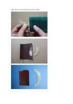
Page 16: ...before assemble Fiber glass servo horns 4 single horns for ailerons and elevator 1 dual horns for rudder There is a layer of protection film on the horns Please remove the film as shown following picture Drill holes with 2 5mm drill ...

Page 17: ...Make sure to sand the horns to keep its strength ...

Page 18: ...Pushrods Two 2 5x60mm for aileron Two 2 5x110mm for elevator you have option to use one or two servos Ball links 8 for aileron and elevator Pull pull setup for the rudder ...

Page 19: ...5 Servo extension safety connector clips Tail wheel assembly Screews for landing gear 4 4x20mm Hexagon socket screw ...

Page 20: ...Screews Washers for cowl 4 3x12mm Hexagon socket screws 4 Washers 4 Hexagon socket screw wrenches Motor mount for brushless motor ...

Page 21: ...n the rudder and trial fit the two control horns 2 Mix up some 30 minute epoxy and coat the inside of the slots and the center of the control horns Hint a scrap piece of 1 16 ply tooth pick or old hobby blade can be used to coat the inside of the aileron slots Slide the control horns in place and make sure they are centered perfectly by using a ruler to measure between the pivot holes and the hing...

Page 22: ...e side of the hinges Install this end into the slots of the rudder and make sure each hinge is properly aligned at exactly 90 degrees to the hinge line 6 Now coat the other end of the hinges with epoxy and install the aileron into the trailing edge of the wing Again make sure the hinges remain in proper alignment Using paper towels and some isopropyl alcohol clean off any excess epoxy from the hin...

Page 23: ... then assemble and adjust the length of each control rod The servo arm should be as close to perpendicular to the control rod as possible while the aileron is at neutral Double check all screws bolts and nuts to assure proper installation and operation without binding Once satisfied permanently attach the ball link to the servo arm with the supplied screw and nut 9 Check the final radio operation ...

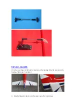
Page 24: ...Elevator Assembly 1 Cut the covering over the hole for elevator on the fuselage Glue the elevator to the fuselage Make sue it s centered 2 Glue the hinge for the elevator the same way as the main wings ...

Page 25: ...ntrol rod and ball links and adjust the control linkage for proper geometry When satisfied screw the ball link to the servo arm The servo arm should be as close to perpendicular to the control rod as possible while the elevator is at neutral Double check all screws bolts and nuts to assure proper installation and operation without binding Below long ALU arm is not included ...

Page 26: ...artment to the aft openings 5 There is an option to use one servo or two servos for the elevator If using one servo the 2 parts of the elevator need to be connected by the wood block with glue as shown below The picture is for illustration only Actually the connection of the 2 parts needs to be performed in the fuselage after the hinges are connected ...

Page 27: ...locker before tightening 2 Then insert another wheel collar in to other end of the tail landing gear and insert the tail gear holding plate Bend the tail wheel wire direction 90 degrees to the tail wheel 3 According to the above tail wheel wire bending length drill 2mm hole in th rudder cut the skin use 30 minute epoxy to the tail wheel wire rack on the rudder ...

Page 28: ...l three 1 5mm holes in the bottom of the fuselage using three self tapping screws to attach the tail wheel holding plate fixed to the fuselage 5 The following photo is the tail wheel assembly installed after ...

Page 29: ... pull pull cable set threaded couplers brass swaging tubes and ball links If the cable is one long piece cut it into two equal length pieces Thread one end of the one cable through a brass tube and then through one of the threaded couplers Run the cable back through the brass tube and then loop it back through a second time Using a set of crimping pliers place three crimps just tight enough not ...

Page 30: ... the threaded coupler Holding the rudder centered adjust the cable length as tight as possible while checking the ball link position over the servo arm When satisfied with the position pinch the cable around the threaded coupler and then feed the loose end back through the brass tube Loop the cable back through the brass tube as before and crimp the brass tube three times just tight enough not to ...

Page 31: ...ylon insert lock nut Install one wheel collar onto the axle Use a second wheel collar as a guide to leave a gap on the inboard of the axle Use a small drop of thread lock and tighten in place Slide the wheel onto the axle and install a second wheel collar also using thread lock on the set screw ...

Page 32: ...t in place and install using the two supplied screws Use thread lock to secure the screws in place Repeat the above steps for the other main gear 3 Bolt the main gear to the bottom of the fuselage using the supplied bolts ...

Page 33: ...ess motor there is an adjustable motor mount in the package 3 First install the motor mount on the firewall Then install the motor Adjust the motor mount to fit the cowl 4 After adjusting the motor mount to the right position lock the 4 screews unscreew them apply 30 minute epoxy and tighten the screws to the previously found position ...

Page 34: ...5 Fix the battery with Velcro 6 The following pictures show how to install gas engine ...

Page 35: ...pe to mark the positions to drill holes for screws on the cowl Drill the holes with 3mm drill Use the 4 3x12mm Hexagon socket screws washers to secure the cowl Use a small drop of thread lock to secure the cap head screws in place ...

Page 36: ...e top quality and connectors are tight and display no loose pins or frayed wires Servo clips are provided in the kit for your convenience These servo clips can even be glued to the wood structure using CA if desired 6 Check all radio programming and control surface operations thouroughly before your initial flight Check your radio range according to the radio manufacturer s instructions both with ...

Page 37: ... onto the fuselage being careful to align the wing tube with the wings and not force it The wing tube may be initially tight but will loosen some with use Guide your servo wires into the fuselage openings and connect to the proper aileron channels Servo clips are recommended Once you have the wings fully seated in the fuselage tighten the wing bolts inside the fuselage 3 Side force generators Asse...

Page 38: ... stabilizers install them once again and check all bolts and connections 7 Check all control surfaces for secure hinges by performed a slight tug on the control surfaces and observing if there is any give in the hinges Check all control rods ball links servo screws etc for proper operation and installation 8 Check your batteries and perform a proper range check once again with the engine off and r...

Page 39: ...Wingbag for 20CC Not Included ...

Page 40: ...3in C F Spinner with Alu base for electric Not Included ...

Page 41: ...3in C F spinner for Nitro Gas Not Included ...

Page 42: ......

Reviews: