background image

Specifications for Argus’ Switched Mode Rectifier Cordex 48-1kW Continued


010-606-B1  Rev A  WC 

Page 2 of 3 

Power Module Input 

Voltage: 

208 to 240Vac nominal 

 Extended Operation: 

Low: 150 to 90Vac (power de-rated linearly to 40% output)  
High: 176 to 320Vac (de-rated power factor above 265Vac) 

Frequency: 

50/60Hz nominal (45 to 66Hz) 

Current: 

5.3 to 4.6A (nominal Vac) 
7.4A maximum @150Vac 

Power Factor: 

>0.99 at nominal conditions and 50-100% load;
>0.98 at nominal conditions and 30-100% load

Protection: 

10kA-interrupting capacity fuses in active and neutral lines 

Efficiency: 

>91% at nominal conditions and 50-100% load

Inrush Current: 

 full load steady state current of the rectifier within rated limits 

Start-up Ready Time: 

<5 seconds (excluding soft start) to complete inrush limit routine  
and ac measurement (for OK signal) 

Start-up Delay: 

Programmable up to 120 seconds to enable stagger-start of multiple rectifiers 
and to minimize the effect on a supply source 

Soft Start: 

User adjustable to at least 5 seconds (not including start-up delay time) and is 
determined by output current limit ramp-up 

T.H.D. (Current): 

<5% at 100% load 

Input Transient Suppression: 

Meets ANSI/IEEE C62.41 Category B3 

Input Leakage Current: 

<3.5mA @ 265Vac 60Hz 

Miscellaneous 

MTBF:

>400,000 hours

Dimensions: 

177mm H x 71mm W x 250mm D (excluding connector) 
[6.9" H x 2.8" W x 9.8" D] 

Weight: 

2.9 kg (6.4 lb.) 

Environmental 

Temperature 

 Operating: 

-40 to +50°C (-40 to 122°F)

 Extended: 

400W @ +65°C (149°F) 

 Storage: 

-50 to +85°C (-58 to 185°F)

Humidity: 

0 to 95% non-condensing 

Elevation: 

-500 to +4000m; derate @ -4°C/1000m above sea level
(-1640 feet to 13124 feet; derate @ -7.2°F/3281 feet above sea level)

Summary of Contents for ALPHA OUTBACK ENERGY Cordex 48-1kW

Page 1: ...Cordex 48 1kW 19 Shelf Flush Mounting Up To 3000W With Distribution 030 713 B2 ...

Page 2: ...ights reserved Headquarter Germany Hansastrasse 8 D 91126 Schwabach Tel 49 9122 79889 0 Fax 49 9122 79889 21 Mail info alpha outback energy com France and Benelux fbnl alpha outback energy com Spain spain alpha outback energy com For more information please visit www alpha outback energy com Russia russia alpha outback energy com Africa africa alpha outback energy com Eastern Europe ee alpha outba...

Page 3: ...tion required for installation operation and fault diagnosis of the unit Specifications 19 Shelf 030 713 B1 Specifications Rectifier 010 606 B1 010 566 20 pre RoHS CSA NRTL Equivalence 048 554 10 Installation and Operation Instructions 030 713 C0 Schematic 030 713 05 Outline Drawing 19 Shelf 030 713 06 Customer Connections 030 713 08 Warranty and Service Information 048 700 10 Service Centers 048 ...

Page 4: ...50 W x 11 94 D rectifier front panel 0 73 D Mounting 19 flush Weight 7 3 kg 16 lb Connections AC Input Terminal blocks 4 to 6mm2 12 to 10AWG Chassis ground 1 4 20 stud Communications CAN bus out RJ 12 offset Ethernet RJ 45 DC Output 1 4 20 x 5 8 studs Signal wiring Terminal blocks 0 14 to 0 75mm2 26 to 18AWG Safety CSA C22 2 No 60950 1 03 UL 60950 1 1st Edition CE EN 60950 CB Scheme 73 23 EEC Low ...

Page 5: ...nd can radiate radio frequency energy and if not installed and used in accordance with the instructions may cause harmful interference to radio communications However there is no guarantee that interference will not occur in a particular installation If this equipment does cause harmful interference to radio or television reception which can be determined by turning the equipment off and on the us...

Page 6: ...age tones Dimensions 177mm H x 74mm W x 255mm D 6 9 H x 2 9 W x 10 D Weight 2 2 kg 5 lb Mounting Modular on Cordex 4RU series 1kW shelves Relay Outputs Eight 8 Form C 60Vdc 1A maximum Digital Inputs Three 3 0 to 60Vdc Analog Inputs and System Signals standard for List 120 Two 2 DC voltage LVD1 K1 Form C relay 60Vdc 1A maximum Load Voltage V1 0 to 100Vdc One 1 current 50mV Two 2 temperature 0 to 20...

Page 7: ...r more EMC In accordance with FCC requirements we provide the following statement as specified in the FCC guidelines for conformance to Part 15 Class B NOTE This equipment has been tested and found to comply with the limits for a Class B digital device pursuant to part 15 of the FCC Rules These limits are designed to provide reasonable protection against harmful interference in a residential insta...

Page 8: ... seconds excluding soft start to complete inrush limit routine and ac measurement for OK signal Start up Delay Programmable up to 120 seconds to enable stagger start of multiple rectifiers and to minimize the effect on a supply source Soft Start User adjustable to at least 5 seconds not including start up delay time and is determined by output current limit ramp up T H D Current 5 at 100 load Inpu...

Page 9: ...al Fast Transient Burst Immunity EN 61000 4 5 Power Line Surge Immunity EN 61000 4 6 Conducted Electromagnetic Immunity EN 61000 4 11 Voltage Dips Short Interruptions and Variations ETS 300 019 1 1 Environmental Conditions Storage ETS 300 019 1 2 Environmental Conditions Transportation ETS 300 132 2 Power Supply Interface at the Input to Telecommunications Equipment Operated by Direct Current DC E...

Page 10: ...t do they do NRTLs are third party organizations recognized by OSHA US Department of Labor under the NRTL program The testing and certifications are based on product safety standards developed by US based standards developing organizations and are often issued by the American National Standards Institute ANSI 4 The NRTL determines that a product meets the requirements of an appropriate consensus b...

Page 11: ...of use of the product 3 Before using the product read all instructions and cautionary markings on the product and any equipment connected to the product 4 Do not expose the product to rain or snow install only in a clean dry environment 5 CAUTION Unless otherwise noted use of an attachment not recommended or sold by the product manufacturer may result in a risk of fire electric shock or injury to ...

Page 12: ...3 Digital Input Channels 8 3 4 Alarm and Control Output Relays 8 3 5 System Fail Alarm Relay 8 3 6 Network Connection and Remote Communications 8 4 INSPECTION 9 4 1 Packing Materials 9 4 2 Check for Damage 9 5 INSTALLATION 10 5 1 Safety Precautions 10 5 2 Shelf Preparation Mounting 10 5 3 Module Insertion Removal 10 6 WIRING AND CONNECTIONS 11 6 1 Safety Precautions 11 6 2 Tools Required 11 6 3 Po...

Page 13: ...nications 19 7 4 Factory Ranges and Defaults 20 8 SYSTEM STARTUP 21 8 1 Check System Connections 21 8 2 Verify AC and Power the Shelf 21 8 3 Check Battery Polarity and Connect 21 8 4 CXC Reset 21 9 MAINTENANCE 22 10 ARGUS CONVENTIONS 23 10 1 Numbering System 23 10 2 Acronyms and Definitions 23 ...

Page 14: ...This page intentionally left blank ...

Page 15: ...lectrical services Rectifier power modules are hot swappable meaning they can be inserted or removed from the shelf without cutting power to or from the system or the load Additional power modules can be included with the system at the time of ordering or added after the shelf has been installed The integrated shelf rectifier system is designed to operate with the Argus Cordex CXCM modular version...

Page 16: ...disconnect LVD List 86 and List 87 cannot be ordered together List 87 Rectifier blank plate gray finish List 90 50 Rectifier blank plate charcoal finish List 90 56 Cover ac terminal block List 92 Breaker 4A List 100 Breaker 5A List 101 Breaker 6A List 102 Breaker 10A List 103 Breaker 20A List 104 Breaker 50A List 105 Breaker 60A List 106 Breaker 63A List 107 Cordex 48 1kW rectifier power module 01...

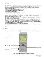
Page 17: ...en is on when AC is within valid range The LED will flash 2Hz when AC is outside the nominal range AC voltage is invalid if the AC Mains Low or AC Mains High alarm is active The LED turns off when AC has failed 2 1 1 2 DC ON The middle LED green is on when the rectifier is delivering power to the load The LED will flash when communication is lost The LED turns off when the rectifier is off e g whe...

Page 18: ...2 5 of the rated output a low output current condition is detected and the Module Fail detection circuit is activated This circuit momentarily ramps up the output voltage to determine if the module will source current If no increase in current is detected the Module Fail alarm is activated The module will test once every 60 seconds for the condition until current is detected Output voltage ramping...

Page 19: ...on determines the maximum output current limit of the module regardless of output voltage or power Maximum output current is limited to a constant value down to short circuit condition Current limiting can be used to mate the rectifier output current ampacity to the needs of the load and parallel battery to minimize excessive battery recharge current The rectifier will sustain a short circuit at t...

Page 20: ...ding easy set up and monitoring using an Internet connection with the standard Windows Internet Explorer browser The data logging feature allows the user to capture data from multiple inputs for AC DC voltages load battery current cell voltages temperatures automatically for up to 16 user defined logs Typical applications of the CXCM logging include power system details thermal performance of outd...

Page 21: ... is designed for CXCM connection to a user supplied network TCP IP secured by user via a rear panel RJ 45 jack and a standard network cable Local access e g laptop computer is also possible from the Ethernet port connection using a standard network crossover cable 3 1 5 RS 232 Serial Craft Port Local access to the CXCM is possible through a front panel RS 232 serial port using a null modem cable T...

Page 22: ...trol and distribution alarm card This provides a safety measure to protect against load disconnect during CXCM reset or replacement e g when the controller is off line Operators may also perform test and maintenance procedures on the CXCM without disturbing the load 3 5 System Fail Alarm Relay The CXCM system fail alarm K0 activates because of a major internal failure During such a condition the u...

Page 23: ... be packaged in its original shipping container If the original container is unavailable make sure the product is packed with at least three inches of shock absorbing material to prevent shipping damage NOTE Argus Technologies is not responsible for damage caused by the improper packaging of returned products 4 2 Check for Damage Prior to unpacking the product note any damage to the shipping conta...

Page 24: ...mounting in a standard EIA 19 relay rack See drawing 030 713 06 NOTE The shelf shall be mounted in a clean and dry environment Allow at least 1 75 of free space around the unit for unrestricted convection cooling airflow Mounting brackets accommodate either 1 or 1 3 4 rack spacing The shelf should be mounted to the rack using at least two 12 24 x 1 2 screws in each bracket Philips type screws and ...

Page 25: ...uilding s ground grid Both the shelf chassis ground via power system chassis ground and common return shall be connected to the site ground to ensure correct operation of the system and to prevent drifting floating analog especially current readings 6 4 AC Feeder Protection Sizing An individual AC feed is provided for each of the three rectifiers It is recommended for each feed to use a dedicated ...

Page 26: ...r the installation application Consult local electrical codes NEC CEC etc for guidelines If required increase the size of the cable to meet the code 6 7 DC Output Connections WARNING Leave cables or bus bars disconnected at battery and verify output polarity using a voltmeter Make battery connections only after all other wiring is completed DC output wire shall be UL approved XHHW or RHH RHW for C...

Page 27: ...nsing wires must be connected to the outputs of installed circuit breakers along with the load and battery feed cables Route wires on this side of the distribution module toward the rear of the shelf Alarm sense wires labeled with a B tag should only be used with battery breakers 6 8 CAN Serial Port A single CAN Serial port RJ 12 modular jack with offset latch is provided for communications with A...

Page 28: ...twork cable 6 9 2 Ethernet Port for Local Connection Crossover Cable Local access e g laptop computer is also possible from the Ethernet port connection using a standard network crossover cable 6 9 3 RS 232 Serial Craft Port for Local Connection Local access to the CXCM is possible through the front panel RS 232 serial port using a null modem cable Figure 6 Null modem pinouts 6 10 CXCM Battery 48V...

Page 29: ...NO 60Vdc 1A Digital Inputs See Table B for definitions of logic and system P5 1 2 D1 Distribution Fuse Alarm Pos or Neg 0 60Vdc P5 3 P6 1 D2 Distribution CB Alarm Pos or Neg 0 60Vdc P6 2 3 D3 Battery CB Alarm Pos or Neg 0 60Vdc Analog Inputs and System Signals E1 Battery 48V Neg 20 60Vdc J3 Ethernet port N A N A P1 2 1 K1 LVD1 Pos Neg 0 60Vdc 1A P7 2 1 V1 Load Voltage Pos Neg 0 100Vdc P8 2 1 I1 Lo...

Page 30: ...ntrol function This is a safety measure to protect against accidental load disconnect should the CXCM be removed from the shelf This protection is also necessary during CXCM reset The OUT voltage is 46V and the IN voltage is 51V Ensure the CXCM LVD voltages are set outside of this range Note controller Relay 1 must be set to ENERGIZED for the LVD to operate properly 6 11 1 2 System Fail Output Ter...

Page 31: ...erminal for CXC reference when a battery disconnect device is used It is critical to CXC operation as it ensures a source of power to the CXC should the disconnect device open the circuit 6 11 3 1 Voltage Voltage Input 1 load voltage per CXC software terminals V1 on the shelf provide connections to an optional secondary voltage input Voltage Input 2 battery voltage per CXC software is wired intern...

Page 32: ...the next state When in this state the CXC continues to monitor its inputs After the Start Delay state the rectifier will transition to the Soft Start state NOTE Soft start or current walk in gradually increases the voltage and current output of the rectifier upon startup This is done to reduce the instantaneous load on the AC source 7 1 3 Soft Start State When the Soft Start state is entered the r...

Page 33: ...of the standard adjustment ranges Table C Output voltage modes 7 2 2 Output Current Power Modes These modes directly affect the output current and power The following table lists the four Output Current Power Modes and a description of when they are active Output Current Power Mode Active when Temperature foldback mode Output current and power limit have been reduced due to high temperature of the...

Page 34: ... 0 100 100 Module Start Delay 0 250s 1s System Start Delay 0 600s 0s Low Voltage Alarm 42 52V 44V High Voltage Alarm 52 63V 55 5V Equalize Timeout 1 2399h 30h Battery Test Timeout 1 250h 8h Softstart Ramp rate Normal Fast Normal CL PL Alarm Enable Disable Enable Remote Shutdown Enable Disable Enable Ramp Test Enable Disable Enable Table E Cordex 48 1kW Rectifier factory ranges and defaults NOTE OV...

Page 35: ...larms and controls 8 3 Check Battery Polarity and Connect Verify correct battery polarity using a voltmeter ensuring no cells or batteries are reversed Connect battery as required to the output of the system or turn on battery breaker Install remaining power modules In the adjustments menu of the CXCM set Float and Equalize voltage to the levels specified by the battery manufacturer Using the CXCM...

Page 36: ...nce a year WARNING HIGH VOLTAGE AND SHOCK HAZARD Use extreme care when working inside the shelf while the system is energized Do not make contact with live components or parts Circuit cards including RAM chips can be damaged by static electricity Always wear a grounded wrist strap when handling or installing circuit cards Procedure Date Completed Clean ventilation openings Inspect all system conne...

Page 37: ...g system for all components and sub assemblies Each part is covered by its own unique number Due to the quantity categories will not be listed within this manual 10 2 Acronyms and Definitions AC Alternating current AWG American wire gauge CAN Controller Area Network CEC Canadian Electrical Code CSA Canadian Standards Association CX Cordex series e g CXC for Cordex System Controller DC Direct curre...

Page 38: ...03071305B__ sch 1 Mon May 14 15 17 29 2007 ...

Page 39: ...03071305B__ sch 2 Mon May 14 15 17 32 2007 ...

Page 40: ... TYPE B SHEET TITLE ISSUE D A T E OF TOLERANCES SCALE APPROVED CHECKED DRAWN DESIGN MATERIAL FINISH FOR MANUFACTURING WITHOUT ITS WRITTEN CONSENT ARGUS TECHNOLOGIES AND SHALL NOT BE COPIED OR USED THESE DESIGNS AND SPECIFICATIONS ARE THE PROPERTY OF REVISIONS LTR DESCRIPTION APPD DATE REV X X 0 04 X XX 0 02 X XXX 0 01 X 1mm X X 0 5mm X XX 0 25mm 030 713 06 OUTLINE SHELF 19 FLUSH MOUNT 3 MDL w CXC ...

Page 41: ...OGIES AND SHALL NOT BE COPIED OR USED THESE DESIGNS AND SPECIFICATIONS ARE THE PROPERTY OF REVISIONS LTR DESCRIPTION APPD DATE REV X X 0 04 X XX 0 02 X XXX 0 01 X 1mm X X 0 5mm X XX 0 25mm 030 713 08 CUSTOMER CONNECTION 3MDL CXC DIN DISTRN 48 1KW 1 3 DGW EOF 2004 09 2004 09 D2 c 2004 ARGUS TECHNOLOGIES O B WES 2004 09 NTS REV BY B ADDED LIST 80 S D W REAR VIEW BACK COVER REMOVED 0 875 KNOCKOUTS AC...

Page 42: ...P4 60V TEMP GP3 N A 0 60V GP2 TEMP 0 60V GP1 TEMP 0 60V BATTERY 48V CONNECT TO BATTERY ONLY WHEN USING BATTERY DISCONNECT DEVICE N0 23 C 24 NC 25 D3 D2 D1 SYSTEM FAIL OUTPUT DIGITAL INPUTS 0 CURRENT INPUT 1 VOLTAGE INPUT 1 I1 I1 V1 V1 LVD CONTROL P6 P5 P8 P7 P1 E1 TOP VIEW CXC BACKPLANE 707 340 20 SOME DETAILS OMITTED J3 1 1 1 1 1 LIST 0 3 MDL e w CXC SIZE DWG NO TYPE B SHEET TITLE ISSUE DATE OF S...

Page 43: ...ITTEN CONSENT ARGUS TECHNOLOGIES AND SHALL NOT BE COPIED OR USED THESE DESIGNS AND SPECIFICATIONS ARE THE PROPERTY OF REV 030 713 08 CUSTOMER CONNECTION 3MDL CXC DIN DISTRN 48 1KW 3 3 D2 B NTS LOAD BREAKERS BATTERY BREAKERS LIST 84 4 LOAD POS N 2 BATTERY POS N COMMON DISTRN BLOCK 6 POSITION CIRCUIT BREAKER HOT OUTPUTS LIST 83 5 LOAD POS N 1 BATTERY POS N BATTERY BREAKER LOAD BREAKERS CIRCUIT BREAK...

Page 44: ...This page intentionally left blank ...

Page 45: ... used whenever possible The box should be completely enclosed and constructed of wood or double wall corrugated cardboard At least 3 of foam or shock absorbing packing material must surround the unit Both the shipping documents and the outside of the box must have the SRO clearly marked and the product shipped prepaid to the AOE factory service center AOE will endeavor to repair products within fi...

Page 46: ... reserved Headquarter Germany Hansastrasse 8 D 91126 Schwabach Tel 49 9122 79889 0 Fax 49 9122 79889 21 Mail info alpha outback energy com France and Benelux fbnl alpha outback energy com Spain spain alpha outback energy com For more information please visit www alpha outback energy com Russia russia alpha outback energy com Africa africa alpha outback energy com Eastern Europe ee alpha outback en...

Reviews: