3.3.02
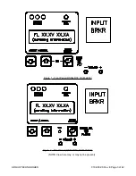
Status Mode Indicators
The indicators provide visual indication of operational status and alarms. The conditions and associ-
ated colors are:
Module Status - OK
. . . . . . . . . . . . . . . . . . . . . . Green
Module Status - Micro-Controller fail/reset
. . . . . Red
Module Status - Alarm Condition Present
. . . . . Yellow
Module Fail
. . . . . . . . . . . . . . . . . . . . . . . . . . . . . Red
Note that the Red Module Status - Micro-Controller fail/reset indicator is located behind the
frosted panel between the Green Module Status - OK and Yellow Module Status - Alarm Condi-
tion Present
indicators and is normally not visible.
3.3.03
Status Indicator - Module OK
When both circuit breakers are closed and no alarm conditions are present the Module Ok indicator
will light. The indicator will not illuminate if a local operator is adjusting or interrogating the unit. Re-
mote or local access of module status does not affect module status. Remote adjustments will af-
fect the indicator.
3.3.04
Status Indicator - Alarm Condition Present
Any alarm condition will cause the Alarm Condition Present indicator to illuminate. Local adjust-
ment or entry into some of the menu modes (except status mode) will cause the LED to illuminate.
The indicator will continue to illuminate any time the criteria is meet and an external voltage is pres-
ent at the modules output. The indicator will not function if the micro-controller fails or is in reset.
Associated with the indicator is a minor alarm contact on the equipment shelf. A minor alarm condi-
tion on any module in a shelf will cause the relay to energize.
3.3.05
Status Indicator - Micro-Controller Fail / Reset
Located in between the Module Status - Ok and Alarm Condition Present indicators is a sepa-
rate Microcontroller Fail/Reset indicator to illuminate in the unlikely event that the micro-controller
fails. Failure of the micro-controller to respond to a watch-dog timer triggers the alarm. The LCD will
be suppressed during this mode of failure. The minor alarm contact at the shelf level will energize in
the event of a micro-controller failure on one of the modules. The indicator will continue to illuminate
any time the criteria is met and an external voltage is present at the module's output.
3.3.06
Module Fail Indicator
Located to the right of the status indicators is a separate Module Fail indicator. If any of the condi-
tions defined as a module failure (see True Module Fail Alarm) occur the indicator will illuminate.
The module fail relay is de-energized while the indicator is on. The indicator will continue to illumi-
nate any time the criteria is met and an external voltage is present at the module's output.
3.3.07
Float Mode
Normal operation of the module is in the FLOAT mode. The module will default to this mode when
A.C. power is supplied to the unit. When in the FLOAT mode the output voltage of the module is
determined by the FLOAT VOLTAGE setting found in the submenu ADJUSTMENTS. The
Float/Equalize
mode control button (labelled Enter/Select) manually returns the unit to the FLOAT
mode from a locally initiated EQUALIZE. FLOAT mode is indicated by illumination of the FL beside
the output voltage reading on the LCD display. The level is protected by fail safe circuitry in the un-
likely event of micro-controller failure.
010-030-C0 Rev E Page 6 of 42
ARGUS TECHNOLOGIES


