7.2
Float Voltage
If sense lines are used the load voltage should be measured with an external meter. Voltage setting
should be done using the external meter at the remote sense point.
First set the Float voltage with the output breaker open. Open the output breaker and select the
FLOAT ADJUST
mode. Entrance to this mode may be prohibited by the presence of a remote
“Equalize” signal. While observing the front panel meter or a DVM on the front panel test points, ad-
just the output level via the Up or Down Adjust/Scroll keys. Accuracy of this setting will be
+/-100mv. Close the output breaker. If greater accuracy is required an external meter should be
used to “fine tune” the setting. The external meter should be monitoring the termination point of the
sense lines. Adjust the FLOAT level as required as described in the initial setting section.
The FLOAT level should not be adjusted when the Module is in current limit.
FLOAT
and EQUALIZE settings do not interact and therefore may be set at any point; however it is
standard practice to adjust the equalize level higher than the float level.
7.3
Equalize Voltage
First set the equalize voltage with the output breaker open. Open the output breaker and select the
EQUALIZE ADJUST
mode. While observing the front panel display, adjust the output level via the
Up
and Down keys. Accuracy of this setting will be +/-100mv. Close the output breaker. If greater
accuracy is required an external meter should be used to “fine tune” the setting. The external meter
should be monitoring the termination point of the sense lines. Adjust the EQUALIZE level as re-
quired.
The EQUALIZE level should not be adjusted when the Module is in current limit.
7.4
Current Limit
The method of setting of the CURRENT LIMIT level is similar to FLOAT and EQUALIZE.
To accurately test the current limit of the Module it is necessary to increase the output current of
the unit to greater than the desired current limit point. The possible methods are:
- Via a dummy load with selectable load settings.
- By turning off other Modules in a multi-Module arrangement to force the unit under
adjustment to take on a greater load.
- If a battery is used the output current can be increased by placing the Module
in the EQUALIZE mode.
While observing the output current reading increase the output current via methods described
above to the desired set point for current limit. When reached the CL indication will appear beside
the output current.
7.5
Test Voltage
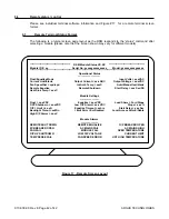
The TEST modes can only be entered if the D.C. output breaker is in the Off position. Once in the
MANUAL TEST
mode the output breaker can be closed and the unit operated under control of the
MANUAL TEST
adjustment. The unit will not operate in AUTO TEST with the breaker closed. Se-
lection of the mode is via the TEST submenu . Manual tests requires the operator to vary the level
via the adjustment keys. Auto tests automatically ramps the test voltage to confirm alarm levels.
ARGUS TECHNOLOGIES
010-030-C0 Rev E Page 31 of 42


