3.3.08
Rectifier Fail Alarm
The RST series of rectifiers have a “true” rectifier fail alarm. This alarm provides a true indication of
the rectifier’s ability to source current. When the rectifier’s current output drops below five percent of
the rated output, the rectifier fail detection circuit is activated. The circuit momentarily ramps up the
output voltage by 5% to determine if the rectifier will source current. If no increase in current is de-
tected within ten seconds, the alarm indicator will illuminate and the associated relay will energize.
The rectifier will continually test for the condition until current is detected. The output voltage
ramping is terminated upon detection of current.
3.3.09
Low Voltage Alarm
When the output of the rectifier drops to the level set by the low volts alarm adjustment potentiome-
ter, the alarm indicator will illuminate and the associated relay will de-energize. When the output
level is raised above the alarm level, the alarm and indicator will extinguish.
3.3.10
Current Limit
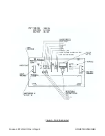
The current limit circuit of the RST rectifier provides a primary response to output overcurrent situa-
tions by limiting current rather than tripping the output breaker. The level at which the current limit
engages is set by the current limit adjust potentiometer on the front panel. When the output current
reaches the preset level the output voltage will decrease and limit the output current of the unit. The
current limit LED on the front panel will also illuminate in conjuction with the closure of the current
limit relay contacts.
3.3.11
Over Voltage Shutdown
The over voltage protection feature electronically shuts down the the rectifier when a high voltage
condition on the output of the rectifier is identified. This is indicated by a front panel LED. The level
of the high voltage shutdown condition is set by the over voltage control on the front panel. This
feature provides protection to the load from a over voltage condition from the power source. The
over voltage shutdown feature of the RST is selective and operates at 5% higher voltage in a no
load condition. This provides the ability to isolate and shutdown a malfunctioning unit amongst a
group of units operating in parallel.
3.3.12
Remote Equalize
When the external positive or negative polarity (with respect to the remote common termination) DC
signal is applied to the remote “Equalize” input, the unit will enter the “Equalize” mode. The re-
sponse to the external signal will be the same as if the front panel “Equalize” mode selection button
was depressed. Upon removal of this signal the rectifier will automatically go into “Float” mode,
even though it may have been in “Test” mode prior to signal application.
3.3.13
Remote Shutdown
When a signal is applied, the unit “electronically” shuts down (breakers are not tripped). To the ob-
server the units appears as if the output breaker was turned off. All the appropriate trouble alarms
are signaled, such as rectifier fail. Removal of the signal will return the rectifier to the condition prior
to signal application. The feature requires the same type of input that is used for remote “Equalize”.
Document #010-002-C0 Rev. H Page 4
ARGUS TECHNOLOGIES
Summary of Contents for RST 48/30
Page 1: ...RST 48 30 Switched Mode Rectifier Eliminator 010 006 B0 ...
Page 24: ...Document 010 002 C0 Rev H Page 14 ARGUS TECHNOLOGIES Figure 3 Front Panel Layout ...
Page 52: ......
Page 53: ......
Page 63: ......
Page 75: ......


