3.3.14
Remote Restart
After over voltage shutdown this feature can be used to attempt a restart of the rectifier. Upon re-
start, the rectifier will reset the high voltage shutdown control. If the condition has cleared, the recti-
fier will resume normal operation. If the condition is still present then the unit will shutdown again
and await a restart signal. Since the restart function is edge sensitive to the control signal, the unit
will not continually attempt to restart. Remote restart requires the same type of input that is used for
remote “Equalize”.
3.3.15
Start Delay
The units are equipped with a delay timer in order to prevent excessive loading of the remote site
standby generators upon start up. The timer delays the AC start of the rectifier depending on the
setting of the start delay selector on the front panel. Delay times from 0 - 90 seconds (in 10 second
increments) are available. The timer will be enabled if any setting besides zero is selected. How-
ever, even in the zero delay position a one second delay is introduced to allow for charging of the
unit’s capacitors prior to initiation of the soft start. Delay will be initiated upon application of AC. At
the end of the delay period the soft start is initiated and the rectifier goes into “Float” mode.
3.3.16
Soft Start
To eliminate an instantaneous demand on the AC supply upon application of AC power, the units
employ a soft start feature sometimes referred to as a “Current Walk-in”. The output of the rectifier
is gradually ramped up from zero amps to the load requirement (100% max). This ramping (33%
per second) is accomplished by current limiting the output.
3.3.17
Output Slope
RST rectifiers use “output slope” also known as “regulation offset” to accomplish load sharing.
When the rectifiers are run in parallel the units must be adjusted to track to each other or share the
load over the output current range. Output slope adjustment alters the regulation curve of the recti-
fier (0.0% preset factory setting).
3.3.18
Input/Output Circuit Breakers
Every unit is equipped with a thermal-magnetic circuit breaker on the input and magnetic breakers
on the output. Excessive current passing through a breaker will result in the breaker releasing to the
tripped (reset) position. The breakers must be manually reset to turn the unit back on. Both break-
ers allow the operator to isolate the unit from either the input or output.
3.3.19
AC Low Voltage Shutdown
The unit is electronically protected from low voltage to the input by fault detection circuitry. If the in-
put to the rectifier falls below the lower AC input limit (see specifications), the unit will shutdown.
The unit will resume normal operation immediately upon restoration of normal line conditions.
3.3.20
Front to Back Ventilation
Cooling of the unit is achieved via front to back convection cooling. Cool air is drawn in via the grill
in the front of the unit. The majority of the airflow is directed towards the rear of the unit and over
the heat sinks. The heatsinks are enclosed in a heat chimney which creates a even draw of cool air
over the fins and out the top rear of the unit. Some of the air flow is drawn over and up through
openings in the main power circuit board, into transformers and around filter capacitors. This sec-
ondary airflow exits via the ventilation holes in the top sides of the unit.
ARGUS TECHNOLOGIES
Document #010-002-C0 Rev. H Page 5
Summary of Contents for RST 48/30
Page 1: ...RST 48 30 Switched Mode Rectifier Eliminator 010 006 B0 ...
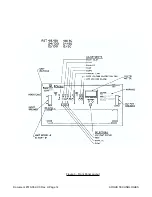
Page 24: ...Document 010 002 C0 Rev H Page 14 ARGUS TECHNOLOGIES Figure 3 Front Panel Layout ...
Page 52: ......
Page 53: ......
Page 63: ......
Page 75: ......


