4.4
Input Connections
4.4.0
Grounding Instructions
This rectifier should be connected to a grounded, metal, permanent wiring system; as an equipment
grounding conductor should be run with circuit conductors and connected to equipment grounding
terminal of the rectifier. Connections to the rectifier should comply with all local codes and ordi-
nances.
4.4.1
Feeder protection/sizing
Each unit should be connected to a dedicated feeder breaker. The units should be connected to
220 Volt or 240 Volt three phase NEC systems (or 120 VAC if equipped - see note below) accord-
ing to the National Electrical Code and all local ordinances. The units should be either permanently
connected according to the National Electrical Code or connected with less than 6 ft of type SJT,
ST, SJO, or SO flexible cord with proper size metal strain relief clamp and appropriately rated UL
approved attachment plug.
120VAC Units: If the unit is used in a multi-unit configuration we recommend that the
208/240 volt (Delta) operation option be used. Optimum power factor will be maintained with
a a 208/240 VAC source. Use of a WYE derived 120 VAC source can result in higher neutral
currents due to the lack of the inherent cancellation effect of third harmonic currents of a
Delta connection. Note that a higher capacity service breaker is required for the unit if the
120 volt source is used - check the specifications for the recommended service breaker rat-
ing.
The minimum size of feeder breaker and wire size is given in the specifications. If larger than mini-
mum feeder breaker is used appropriately higher capacity wire size as required according to the
National Electrical Code.
WARNING: The feeder breaker must be in the “off” position before at-
tempting to install the rectifier.
4.4.2
AC Connections
Confirm the operating voltage before proceeding.
WARNING: Ensure that the input and output breakers are in the “off”
position prior to any work being performed on the AC or DC connec-
tions.
AC input wires should be tightly bundled and routed as far away as possible from the power PCB to
minimize EMI pickup on the AC feed wires.
4.4.2.1
Input wires can be routed through the rear or front access holes located on the side of the unit. The
cable clamp plate is for 1/2" conduit or a cable clamp. Select the cable clamp plate shipped at-
tached to the rear access hole, swap with the blank if front access is desired.
4.4.2.2
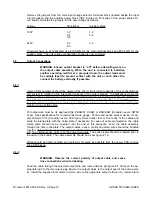
Insert the AC cable through the cable clamp as per figure #1a. Note the length of cable to be used
as indicated in the table.
Document #010-002-C0 Rev. H Page 8
ARGUS TECHNOLOGIES
Summary of Contents for RST 48/30
Page 1: ...RST 48 30 Switched Mode Rectifier Eliminator 010 006 B0 ...
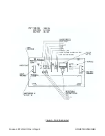
Page 24: ...Document 010 002 C0 Rev H Page 14 ARGUS TECHNOLOGIES Figure 3 Front Panel Layout ...
Page 52: ......
Page 53: ......
Page 63: ......
Page 75: ......


