4.5.3
Secure the control, sense and alarm cables behind the cable clip on the front panel. Insert each
wire into the appropriate terminal on the termination block and tighten.
4.5.4
Re-attach the output cable clamp bracket with the two Philips head chassis screws. Close and se-
cure the front panel in preparation for normal operation.
4.5.5
Connect the output cable to the load or to the appropriate output termination bars. If the output is
connected to a battery or to parallel operating rectifier(s), the rectifier fail indicator should come on
for all 48V and positive ground units.
Positive Ground Units Only:
WARNING: On units used in a positive ground configuration: if the
rectifier fail indicator does not illuminate and the external DC power
source is present, refer to the trouble shooting section immediately
before proceeding to the next section. Output polarity could be re-
versed, resulting in damage to the unit.
All Units:
WARNING: On units, confirm that the output polarity connection is
correct to prevent damage to the load or the rectifier.
Due to the location of the output circuit breaker and diode used on units in a negative ground appli-
cation, the rectifier fail indicator does not illuminate with the input and output breakers in the OFF
position. Remote indication of the rectifier fail condition is provided by the fail safe nature of the
alarm contacts.
4.6
Initial Start-up
WARNING: The output breaker should be off prior to application of AC
power.
To adjust all settings the use of a small pocket screw driver or tweaker is recommended.
For all controls, to increase a level, the corresponding adjustment control is rotated clockwise. To
decrease a level the corresponding adjustment control is rotated counter-clockwise.
4.6.1
AC Start-up
Apply AC power via the feeder breaker, then place the rectifier’s input breaker in the the “on” posi-
tion. The “Float” ,"Power on", and “Rectifier fail” indicators should all be lit. If the delay timer control
is set to any position other than zero, the rectifier will not start until the selected delay has elapsed.
Document #010-002-C0 Rev. H Page 12
ARGUS TECHNOLOGIES
Summary of Contents for RST 48/30
Page 1: ...RST 48 30 Switched Mode Rectifier Eliminator 010 006 B0 ...
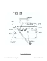
Page 24: ...Document 010 002 C0 Rev H Page 14 ARGUS TECHNOLOGIES Figure 3 Front Panel Layout ...
Page 52: ......
Page 53: ......
Page 63: ......
Page 75: ......


