-Via a dummy load with selectable load settings
-By turning off other rectifiers in a multi-rectifier arrangement to force the unit under adjust-
ment to take on a greater load.
-By placing the rectifier in the “Equalize” mode".
While observing the front panel ammeter decrease the output current via the current limit control to
the desired set point for current limit.
6.3
Float Voltage
To adjust the “Float” and “Equalize” levels with the output breaker “closed”, it is necessary to main-
tain a load of greater than 5% on the output of the rectifier. This load level will prevent the unit from
entering a “rectifier fail” condition.
Unless the load and sense lines are terminated directly to the unit’s output, voltage should be mea-
sured with a external meter. Voltage setting should be done using the external meter at the remote
sense point.
6.3.1
Open the output breaker and select the “Float” mode. While observing the front panel meter, adjust
the output level via the “Float” control potentiometer. Accuracy of this setting will be +50mv
+/-100mv. Entrance to this mode may be prohibited by the presence of a remote “Equalize” signal.
Close the output breaker. If greater accuracy is required an external meter should be used to “fine
tune” the setting. The external meter should be monitoring the termination point of the sense lines.
Adjust the “Float” control as required.
The float level should not be adjusted when the rectifier is in current limit or at no load. When in
current limit, increasing the level will only reduce output voltage. If at no load, increasing the level
will interfere with the rectifier fail detection circuit.
“Float” and “Equalize” settings do not interact and therefore may be set at any point. However it is
standard practice to adjust the equalize level higher than the float level.
6.4
Equalize Voltage
First set the equalize voltage with the output breaker open. Open the output breaker and select the
“Float” mode. While observing the front panel meter, adjust the output level via the “Equalize” con-
trol potentiometer. Accuracy of this setting will be +50mv +/-100mv. Close the output breaker. If
greater accuracy is required an external meter should be used to “fine tune” the setting. The exter-
nal meter should be monitoring the termination point of the sense lines. Adjust the “Equalize” con-
trol as required.
The equalize level should not be adjusted when the rectifier is in current limit or at no load. When in
current limit increasing the level will only reduce output voltage. If at no load, increasing the level
will interfere with the rectifier fail detection circuit.
6.5
Test Voltage
The “Test” mode can only be entered if the DC output breaker is in the “off” position. Once in the
“Test” mode, the output breaker can be closed and the unit operated under control of the “Test” ad-
justment. Selection of the mode is via the “Test” mode switch on the front panel. Adjustment of this
control will be detailed in the under voltage alarm and over voltage shutdown sections.
ARGUS TECHNOLOGIES
Document #010-002-C0 Rev. H Page 17
Summary of Contents for RST 48/30
Page 1: ...RST 48 30 Switched Mode Rectifier Eliminator 010 006 B0 ...
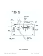
Page 24: ...Document 010 002 C0 Rev H Page 14 ARGUS TECHNOLOGIES Figure 3 Front Panel Layout ...
Page 52: ......
Page 53: ......
Page 63: ......
Page 75: ......


