7.0
Theory of Operation
The RST series are direct off-line switch-mode rectifiers (battery chargers/eliminators) employing
high voltage, high speed switching transistors and high frequency ferrite magnetics to provide a
converted, regulated, isolated, very low noise output.
7.1
Power Circuit
7.1.1
General
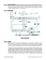
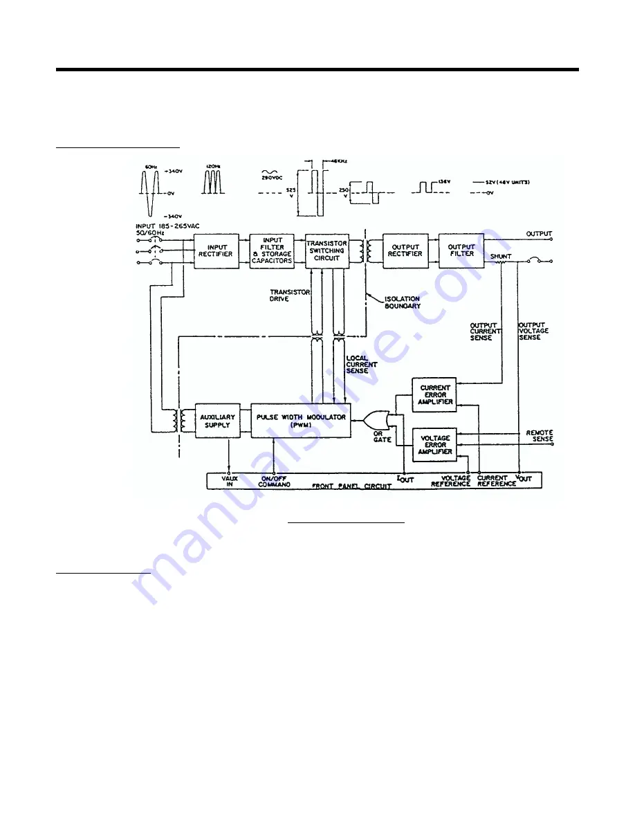
Please refer to the power circuit block diagram (figure 4). The 185-265 VAC 50/60 Hz or VAC,
50/60 3 phase input is fed through a circuit breaker into a 3 phase full wave rectifier which provides
a 120 Hz 340 volt peak pulse train to an input filter circuit. The input filter provides a nominal 290
volts DC “raw supply” with approximately 30 V P-P 120 Hz ripple to the transistor switching circuit.
The transistor switching circuit chops the raw supply into nominally 525 volts P-P, 48 KHz rectangu-
lar waveform with a nominal 39% duty cycle. This waveform is fed into a ferrite power transformer
which steps down and isolates the high frequency switching waveform. A rectifier circuit converts
the power transformer output to a DC pulse train of nominally 136 V peak. A two-stage output filter
averages and smooths this pulse train down to provide the nominal 52 VDC output with low noise.
A voltage error amplifier circuit senses the output voltage and compares it with the voltage refer-
ence to provide a voltage error signal. Similarly, a current error amplifier senses the output current
ARGUS TECHNOLOGIES
Document #010-002-C0 Rev. H Page 21
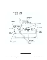
Figure 4 - Block Diagram
Summary of Contents for RST 48/30
Page 1: ...RST 48 30 Switched Mode Rectifier Eliminator 010 006 B0 ...
Page 24: ...Document 010 002 C0 Rev H Page 14 ARGUS TECHNOLOGIES Figure 3 Front Panel Layout ...
Page 52: ......
Page 53: ......
Page 63: ......
Page 75: ......


