7.2.8
Current Limit and Low Current Comparators
Comparator U16/A compares the output current to the current limit point. A point just before the cur-
rent limit is derived from the output of current limit buffer U3/C via a divider consisting of resistors
R61 and R62. The output current information is provided via the power board and filtered by resis-
tor R69 and capacitor C23. The output of U16/A drives the front panel current limit indicator DS10
via inverting buffer U6/E and resistor R58. The current limit remote alarm relay, K3 is driven from
the current limit capacitor U16/A by inverting buffer U6/F. The output current information is also pre-
sented to low current comparator U16/B. The low current point (5% I max) is derived from the auxil-
iary reference via a divider consisting of R63 and R64. The low current information is used by the
rectifier fail and O.V.P. circuitry.
7.2.9
Over Voltage and Undervoltage Circuitry
A reference for overvoltage detection is created from the auxiliary reference via front panel control
R87 and resistor R83 and bypass capacitor C28 and is presented to the noninverting input of com-
parator U17B. The output voltage of the unit is sensed via a divider consisting of R79 and R80 with
noise suppressing capacitor C29. The output of U17B, which goes high when an OVP condition is
detected, is coupled to the inputs of NAND gate U18/A which acts as an inverter through D8. The
OVP threshold is shifted up by 5% by transistor Q17 and resistor R124 if the output current is de-
tected to be low through D23 unless the unit is in local sensing as coupled through D24. Thus the
OVP will only trip at low output current in local sensing. The output of U18/A is presented to the set
input of a set-reset latch consisting of NAND gates U18/B and U18/C. The output of the latch,
which goes low on OVP trip, turns off the rectifier by pulling one input of on/off gate U15/A low and
lights the front panel OVP indicator DS9 via transistor Q4 and resistor R57.
The OVP latch is reset if the input power to the unit is turned off via diode D10 from the “power on”
signal or if the remote restart input is activated via diode D9 and optical coupler U21. Pulse network
R88, C31, R89 prevents a continuous reset of the OVP latch if the remote restart input is continu-
ously connected to ground.
A reference for undervoltage detection is presented to the noninverting input of comparator U17/A.
The reference is derived via control R86, resistors R82 and R92 and noise suppressing capacitor
C45. The output voltage of the rectifier is detected via a divider consisting of R113, and R72. Either
the output voltage before or after the output circuit breaker can be selected via jumper, P2 to allow
easy adjustment of the low voltage detector. Resistor R73 provides hysteresis of the under voltage
point to avoid chattering of the under voltage relay K1. When an undervoltage condition is detected
the output of U17/A goes high and transistors Q5 and Q7 are turned off to allow the front panel un-
der voltage indicator DS11 to light and the under voltage relay K1 to de-energize. The contacts of
K1 are extended to customer interface TB1 allowing remote indication of undervoltage or driving of
an undervoltage contactor.
7.2.10
Front Panel Meter and Test Points
A single chip 3 or 3 ½ digit meter U1 is integral to the front panel PCB assembly. It’s time reference
is derived from an integral oscillator utilizing R10 and C46. A one volt reference is derived from the
auxiliary reference via R9, R8 and C5. A -5 volts bias supply is derived from the -12 volt bias sup-
ply via R12, C7 and 5.1 volt zener D2. Capacitor C2 is the hold capacitor while components C3,
C4, and R7 form part of the integrating network. Integrated circuit U1 senses the output current nor-
mally through SW1. If SW1 is pressed the output voltage of the unit is sensed through a divider
consisting of R14 and R5. I.C. U1 drives the 7 segment displays DS1, DS2, and DS3 directly (and
DS12 for 100 Amp units) via current sinking outputs. Diode D1 reduces the dissipation of U1. The
decimal point of DS2 is lit via resistor R111. The majority of the circuitry of U1 and the displays are
powered from the +5 volt bias supply.
ARGUS TECHNOLOGIES
Document #010-002-C0 Rev. H Page 27
Summary of Contents for RST 48/30
Page 1: ...RST 48 30 Switched Mode Rectifier Eliminator 010 006 B0 ...
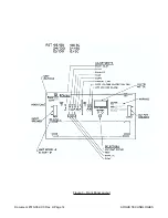
Page 24: ...Document 010 002 C0 Rev H Page 14 ARGUS TECHNOLOGIES Figure 3 Front Panel Layout ...
Page 52: ......
Page 53: ......
Page 63: ......
Page 75: ......


