GB - 10
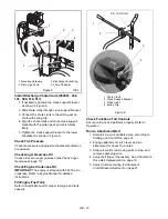
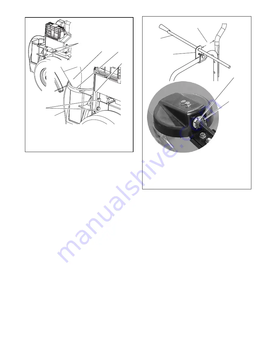
Install Discharge Chute Crank (932041, 042,
141, 509, 510, 511)
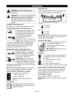
1. If necessary, position the crank support bracket
as shown in Figure 6.
2. Slide chute crank through crank support bracket.
3. Connect the chute crank to the pinion gear on
chute with spring clip.
4. Align the chute crank and chute crank support
bracket with the pinion gear so crank rotates
freely.
5. Tighten the crank support bracket to the lower
handlebar as shown in Figure 6.
Check Tire Pressure
Check tire pressure and adjust to the pressure listed on
tire sidewall.
Check Auger Gearcase Oil
Check oil level in auger gearcase (see Check Auger
Gearcase on page 17).
Check Engine Crankcase Oil
IMPORTANT: The engine is shipped with 5W-30 oil in
crankcase. Refer to Engine Manual for detailed
instructions.
Fill Engine Fuel Tank
Refer to Engine Manual for proper fuel type and tank
capacity.
Check Function of all Controls
Ensure unit runs and performs properly. Refer to
Operation.
Run-in Attachment Belt
1. Start unit in a well-ventilated area according to
Starting and Shut Off on page 14.
2. Engage attachment clutch lever and run
attachment for about 15 minutes.
3. Stop unit, wait for all moving parts to stop, and
remove spark plug wire.
4. Adjust belt finger, if necessary. See Attachment
Drive Belt Replacement on page 19.
5. Adjust clutch according to Attachment
Clutch/Brake Adjustment on page 21.
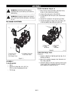
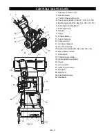
Figure 5
1. Mounting Hardware
2. Discharge Chute
3. Discharge Chute Ring
4. Chute Pedestal
OS6610
OS6620
Figure 6
1. Chute Crank
2. Crank Support Bracket
3. Pinion Gear
4. Spring Clip
2 in. (5.08 cm)
Summary of Contents for 624E
Page 29: ......


