GB - 15
STEERING ADJUSTMENT
If steering system feels loose, ensure hardware is tight
and check wear points for excessive wear. Replace parts
as needed.
If tractor wanders or excessive tire wear develops, toe-in
should be checked. Front of wheels should be 1/16 in. to
1/8 in. (2 to 3 mm) closer together than rear of wheels. To
correct toe-in:
1. Loosen jam nuts at tie rod ends.
2. Turn tie rod clockwise to increase distance between
front of wheels. Turn tie rod counterclockwise to
decrease distance between front of wheels.
3. Tighten jam nuts at tie rod ends.
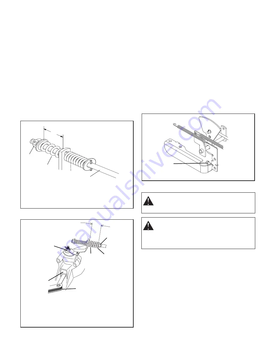
PARKING BRAKE SPRING
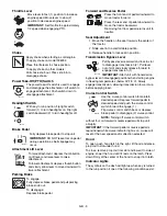
Compress the spring to the length indicated with the
brake on (Park Brake Set). Turn the locknut to adjust
(figure 14).
DISC BRAKE ADJUSTMENT
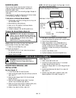
To check and change disc brake setting (figure 15):
1. Place feeler gauge between the two discs. With
clutch/brake pedal released there should be
0.015 in. to 0.025 in. (0.4 mm to 0.6 mm) clearance.
2. Tighten castellated nut to decrease clearance,
loosen to increase clearance.
3. Adjust brake spring. Turn nylon locknut until brake
spring is compressed to 7/8 in. (22 mm) when brake
pedal is depressed.
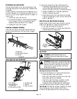
NEUTRAL ADJUSTMENT (936036)
Adjust neutral if tractor moves when forward or reverse
pedal is not depressed. To adjust neutral (figure 16):
1. Prop right rear wheel off the ground.
2. Spin right rear wheel. Turn neutral adjustment bolt
until rear wheel no longer spins.
BATTERY
Battery Electrolyte First Aid
Follow First Aid directions for contact with battery fluid.
•
External Contact: Flush with water.
•
Eyes: Flush with water for at least 15 minutes and
get medical attention immediately!
•
Internal Contact: Drink large quantities of water.
Follow with Milk of Magnesia, beaten egg or
vegetable oil. Get medical attention immediately!
In case of internal contact, DO NOT induce vomiting!
IMPORTANT:
DO NOT fast charge. Charging at a higher
rate will damage or destroy battery. ONLY use an
automatic charger designed for use with your battery.
1-13/16 in. (4.6 cm)
1
2
3
OT0351
Figure 14
1. Brake Rod
2. Compression Spring
3. Lock Nut
1
2
3
4
5
6
OT0840
Figure 15
7/8 in.
22 mm
1. Disc Brake
2. Castellated Nut
w/Cotter Pin
3. Compression Spring
4. Feeler Gauge
5. Washer
6. Nylon Locknut
WARNING:
AVOID INJURY. Read and
understand the entire
Safety
section before
proceeding.
WARNING:
Battery posts, terminals and related
accessories contain lead and lead compounds,
chemicals known to the State of California to
cause cancer and reproductive harm. Wash
hands after handling.
Figure 16
Neutral
Adjustment
Bolt
OT0041


