background image


GB - 16


IMPORTANT: 


ALWAYS follow information provided on 

battery by battery manufacturer. Contact battery 
manufacturer for extensive instructions to charge battery.


Charging Battery


1. Place unit in service position.

2. Disconnect negative (-) cable from battery first, then 

positive (+) cable.

3. Loosen strap and remove battery.

4. Place battery on bench or other well-ventilated 

place.

5. Connect positive (+) lead of charger to positive (+) 

terminal, and negative (–) lead to negative (–) 
terminal.

6. Charge battery according to charger and battery 

manufacturers’ instructions.

7. Reinstall battery into unit and connect positive (+) 

cable first, then negative (–) cable. Position boot 
over positive terminal.


Jump Starting Battery


Jump starting the battery may be required if starter motor 
will not crank the engine.

The unit used for jump starting should have a 12 volt, 500 
cold cranking amperes, negatively grounded system.

1. Disconnect negative (-) cable from battery.

2. Disconnect positive (+) cable from battery.

3. Connect the positive (+) jumper cable to the positive 

terminal of the unit battery.

4. Connect the other end of the positive jumper cable 

to the positive (+) terminal of the booster battery.

5. Connect one end of second jumper cable to the 

negative (-) terminal of the booster battery.

6. Connect the other end of the second jumper cable 

to the furthest ground point from the discharged 
battery.

7. Start the unit.

8. After unit starts, disconnect cables in following 

order: disconnect cable from ground point, 
disconnect negative (-) cable from booster battery 
terminal, disconnect positive (+) cable from booster 
battery terminal, and disconnect positive (+) cable 
from unit battery terminal.

9. Connect positive (+) cable first from unit to battery, 

then negative (-) cable from unit to battery.


Short Term  Storage


IMPORTANT: 


NEVER spray unit with water or store unit 

outdoors.

Remove all dirt, grease, leaves, etc. Store in a clean, dry 
area.

Ensure all fasteners are properly tightened. Inspect 
moving parts for damage and wear.

Clean seat with vinyl cleaner. Apply vinyl repair tape to 
any tears on seat.


Long Term  Storage


Follow all instructions under 


Short Term Storage


.

Remove and fully charge battery. Store in a cool, dry 
location.

Drain fuel from fuel tank.

See engine manual for proper engine storage 
procedures.

Touch up all rusted or chipped paint surfaces.

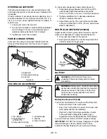
1. Negative terminal
2. Positive terminal

3. Battery

3

1

2

OF1671

Figure 17


WARNING: 


AVOID INJURY. Read and 

understand the entire 


Safety 


section before 

proceeding.


WARNING: 


Frozen battery can explode and 

result in death or serious injury.

DO NOT charge a battery containing frozen 
fluid. Thaw the battery before putting on a 
charger or jump starting.


STORAGE


WARNING: 


AVOID INJURY. Read and 

understand the entire 


Safety 


section before 

proceeding.

Summary of Contents for 936034 - 1540

Page 1: ...Owner Operator Manual Model 936034 1540 936036 2548 Yard Tractor 03695200 10 02 Printed in USA ENGLISH FRANÇAIS ESPAÑOL ...

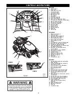
Page 2: ...u siège 12 Désenclenchement de la transmission soupape de décharge 13 Indicateur de hauteur de coupe de la tondeuse 14 Commande du starter 936036 15 Régulateur de vitesse 16 Lampes témoin 17 Pédale de marche avant 18 Pédale de marche arrière 19 Rouleau anti scalp 20 Déflecteur 21 Fermeture du capot ESPAÑOL 1 Llenado del depósito de combustible 2 Pedal del freno 3 Palanca de elevación del accesorio...

Page 3: ... please fill out sign and return the product registration card to Ariens UNAUTHORIZED REPLACEMENT PARTS Use only Ariens replacement parts The replacement of any part on this vehicle with anything other than an Ariens authorized replacement part may adversely affect the performance durability or safety of this unit and may void the warranty Ariens disclaims liability for any claims or damages wheth...

Page 4: ...al purchaser loaned rented or sold ALWAYS provide this manual and any needed safety training before operation SAFETY DECALS AND LOCATIONS ALWAYS replace missing or damaged Safety Decals Refer to figure 3 below for Safety Decal locations 1 DANGER Read the operator s manual Allow operation only by properly trained adult never children DO NOT mow when children or others are around Keep children out o...

Page 5: ...MUERTE TO AVOID SERIOUS INJURY OR DEATH Read the operator s manual Keep children and others away from unit while operating Look down and behind before and while backing Never carry children Never direct discharge toward other people Thrown objects can cause injury Go up and down slopes not across If machine stops going uphill stop blade and back down slowly Avoid sudden turns Keep safety devices g...

Page 6: ...page 8 ALWAYS remove key to prevent unauthorized use DO NOT operate at too fast a rate Slow down before turning Stop engine before removing grass catcher or unclogging chute DO NOT mow on wet grass Reduced traction could cause sliding DO NOT try to stabilize the machine by putting your foot on the ground Know the weight of loads Limit loads to those you can safely control and the unit can safely h...

Page 7: ...es out of reach of children Battery posts terminals and related accessories contain lead and lead compounds chemicals known to the State of California to cause cancer and reproductive harm Wash hands after handling Reverse connections may result in sparks which can cause serious injury Always connect positive lead of charger to positive terminal and negative lead to negative terminal ALWAYS discon...

Page 8: ...d Engine MUST STOP if operator leaves seat when forward and reverse pedal is not in neutral or parking brake is disengaged or PTO is engaged Engine MUST NOT start unless parking brake is set brake pedal is depressed and forward and reverse pedal is in neutral and PTO is disengaged DO NOT operate unit unless safety interlock system is functioning properly If it does not function properly see your A...

Page 9: ...rns unit to neutral Seat Adjustment 1 Move the handle on the seat towards the center of the tractor 2 Slide seat into a comfortable position 3 Release handle to lock seat in position Transmission Bypass Lever Pull bypass lever rearward and lock in slot to disengage transmission 2 Pull lever out of slot and slowly release forward to engage transmission 1 IMPORTANT Start unit with transmission bypas...

Page 10: ...load IMPORTANT Run engine at 1 2 throttle for at least five minutes prior to applying load in freezing temperatures TO OPERATE MOWER 1 With unit shut off adjust deck to desired height of cut 2 Start engine 3 Move throttle lever to about half speed 4 Engage PTO 5 Move the throttle lever forward to full engine speed 6 Use forward and reverse pedals to move and use steering wheel to change direction ...

Page 11: ... to prevent unexpected movement of the unit If the parking brake allows unit movement while engaged for proper parking brake spring setting see Parking Brake Spring on page 15 CHECK FASTENERS Be certain all hardware is tightened to the proper torque Pay special attention to blades guards and safety shields TIRE PRESSURE Check air pressure in all tires every 25 operating hours see Specifications on...

Page 12: ... heavy end until blade is balanced 5 Install mower blade on unit 6 Tighten hardware to 50 60 lbf ft 68 81 N m MOWER DECK REMOVAL AND INSTALLATION Remove figure 7 1 Lower mower deck to lowest position 2 Remove height adjuster link item 8 from center lift lever item 1 3 Remove rear hanger item 3 from rear hanger bracket item 2 4 Remove front hanger bracket item 7 and pin item 5 from slotted bracket ...

Page 13: ...el If mower deck is not level repeat steps 3 through 6 If mower deck is level then adjust pitch of mower deck Adjust Pitch of Mower Deck 1 With the end of mower blades facing forward measure the distance from mower blade and the ground at the front of mower deck figure 9 NOTE Adjust mower pitch so front end of mower blade is 1 8 in to 1 4 in 3 mm to 6 mm lower than back end of mower blade figure 9...

Page 14: ... DECK BELT See figure 11 or figure 12 1 Remove mower drive belt 2 Disconnect idler spring from spring mount welded to the mower deck 3 Remove left sheave cover 4 Remove old belt from mower deck and install new belt Ensure belt is seated in all pulley grooves 5 Replace left sheave cover reconnect idler spring and replace mower drive belt TRACTION DRIVE BELT 1 Loosen hardware securing belt fingers a...

Page 15: ...l if tractor moves when forward or reverse pedal is not depressed To adjust neutral figure 16 1 Prop right rear wheel off the ground 2 Spin right rear wheel Turn neutral adjustment bolt until rear wheel no longer spins BATTERY Battery Electrolyte First Aid Follow First Aid directions for contact with battery fluid External Contact Flush with water Eyes Flush with water for at least 15 minutes and ...

Page 16: ...end of the second jumper cable to the furthest ground point from the discharged battery 7 Start the unit 8 After unit starts disconnect cables in following order disconnect cable from ground point disconnect negative cable from booster battery terminal disconnect positive cable from booster battery terminal and disconnect positive cable from unit battery terminal 9 Connect positive cable first fro...

Page 17: ...s disengaged 2 Clutch needs adjustment 1 Engage transmission using bypass lever 2 See Ariens Dealer Engine runs roughly 1 Choke engaged 2 Air cleaner clogged 1 Disengage choke 2 Replace air cleaner See engine manual ACCESSORIES See your authorized Ariens dealer to add these optional accessories to your unit Part No Description 73600900 Rear Mounted Weight Box 73600200 Tire Chains 20 x 8 8 Tires 73...

Page 18: ...2 Engine hp kW 15 0 11 25 0 19 V Twin Engine Manufacture Briggs Stratton Width of Cut in cm 40 101 48 122 Max Rotation Speed of Cutting Edge min 1 3065 4000 Fuel and Capacity gal L Unleaded 3 11 4 Governed R P M No Load 3200 Max Engine Oil See Engine Manual Transmission Hydro Gear 510 Hydro Gear 327 750 Speed Forward Max MPH km h Reverse Max MPH km h 0 5 5 0 8 9 0 2 5 0 4 Transmission Lube 20W50 O...

Page 19: ...12 months after date of purchase on a prorated basis For the first ninety 90 days of the warranty period a defective battery will be replaced free of charge If the applicable warranty period is more than 90 days Ariens Company will cover the prorated cost of any defective battery for up to twelve 12 months after the date of purchase The following items are not covered by this warranty Engines and ...

Page 20: ...Ariens Company 655 West Ryan Street P O Box 157 Brillion WI 54110 0157 920 756 2141 Fax 920 756 2407 www ariens com ...

Reviews: