23
SERVICE AND ADJUSTMENTS
TO REPLACE HEADLIGHT BULB
• Raise
hood.
• Pull bulb holder out of the hole in the backside of the
grill.
• Replace bulb in holder and push bulb holder securely
back into the hole in the backside of the grill.
• Close
hood.
INTERLOCKS AND RELAYS
Loose or damaged wiring may cause your tractor to run
poorly, stop running, or prevent it from starting.
• Check
wiring.
TO REPLACE FUSE
Replace with 20 amp automotive-type plug-in fuse. The
fuse holder is located behind the dash.
03076
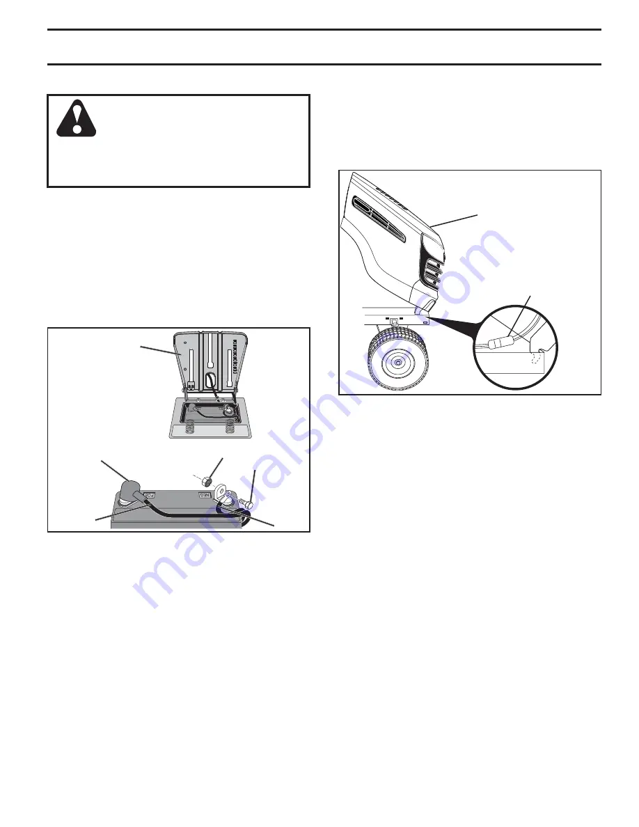
HOOD
HEADLIGHT
WIRE
CONNECTOR
Fig. 37
TO REMOVE HOOD AND GRILL ASSEMBLY
(See Fig. 37)
• Raise
hood.
• Unsnap headlight wire connector.
•
Stand in front of tractor. Grasp hood at sides, tilt toward
engine and lift off of tractor.
• To replace, reverse above procedure.
ENGINE
TO AD JUST THROTTLE CON TROL CABLE
The throttle control has been preset at the factory and
ad just ment should not be necessary. If adjustment is nec-
es sary, see engine manual.
TO AD JUST CHOKE CON TROL
The choke control has been preset at the factory and ad just-
ment should not be necessary. If adjustment is necessary,
see engine manual.
TO ADJUST CARBURETOR
Your carburetor is not adjustable. If your engine does not
operate properly due to suspected carburetor problems,
take your tractor to an authorized service center for repair
and/or adjustment.
Fig. 36
02603
SEAT PAN
NUT
POSITIVE
(RED)
CABLE
NEGATIVE
(BLACK)
CABLE
BOLT
TERMINAL
COVER
REPLACING BATTERY (See Fig. 36)
WARNING: Do not short battery ter mi nals
by allowing a wrench or any other object
to contact both terminals at the same
time. Before connecting battery, remove
metal bracelets, wristwatch bands, rings,
etc. Positive terminal must be connected
first to prevent sparking from ac ci den tal
grounding.
• Lift seat pan to raised position.
•
Disconnect BLACK battery cable first then RED battery
cable and carefully remove battery from tractor.
• Install new battery with terminals in same position as
old battery.
•
First connect RED battery cable to positive (+) terminal
with bolt and nut as shown. Tighten securely. Slide
terminal cover over terminal.
• Connect BLACK grounding cable to negative (-) ter-
mi nal with remaining bolt and nut. Tighten se cure ly.
• Lower seat pan.
Summary of Contents for 936064
Page 28: ...28 SERVICE NOTES ...
Page 33: ...28 REMARQUES D ENTRETIEN ...


