PAGE 1 • 1501264-INS-R
B
•
877.287.8634
• NEED ASSISTANCE?
•
ARIESAUTOMOTIVE.COM
Product Image
Level of Difficulty
Easy
Scan
for helpful
install tips
INSTALLATION MANUAL
1501264
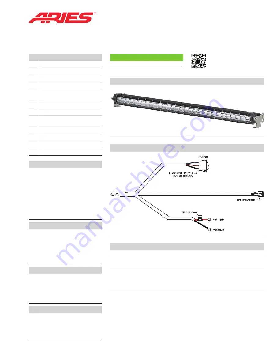
Wiring Diagram
Notes and Maintenance
Before you begin installation, read all instructions thoroughly.
Periodic inspection of all wires and connections should be performed to ensure
there is no visible damage or loose connections.
WARNING:
Improper electrical installation may damage electronic components
resulting in personal injury, property or equipment damage. Damaged caused
by incorrect installation is not covered by warranty. Installation should only be
performed by qualified personnel with asolid understanding of electrical systems.
Step 1
Mount the LED light in the desired
location with a rubber spacer between
the mounting surface and each bracket.
Note:
If this light bar is being used
with a 24V system, the relay will need
to be replaced with a 24V unit.
Disconnect the supplied switch
from the wiring harness and install
in the desired location.
Step 2
Once the LED light bar and switch are
installed, route the wiring harness to
the light. Insert the male plug on the
wiring harness into the female socket
on the LED light. Reconnect the blue,
red and black spade connectors to
the switch (see the wiring diagram).
Step 3
Connect the red fused wire with
the ring terminal to the positive (+)
battery post. Connect the black
wire ring terminal to the negative (-)
battery post or other suitable vehicle
grounding point.
Step 4
Mount the provided relay to the
vehicle and secure all wires with zip
ties away from moving parts to avoid
damage. Test the light to ensure
proper function.
Parts List
1
LED light bar, 10"
1
Mounting bracket, left
1
Mounting bracket, right
1
Wiring harness
2
Security screw,
M6 - 1.0 x 25mm
2
Rubber spacer, M6
2
Flat washer, M6
2
Hex head cap screw,
M8 - 1.25 x 18mm
2
Flat washer, M8
2
Nylock nut, M8 -1.25mm
1
Security screw L-wrench
1
15-amp fuse, pre-installed


