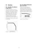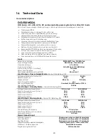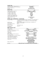
25
12
Output
Configurations
Besides in Standard configuration
described below, DC-UPSs of the same
type can be connected in parallel
configuration to achieve a desired
redundancy level or increase totally
available current.
DC-UPSs can also be connected in series
to power DC buses with voltage rating
higher than those available in the DCU
range. Alternatively, series connection
can be used to achieve higher currents
than at higher voltage
12.1
Standard Output
configuration
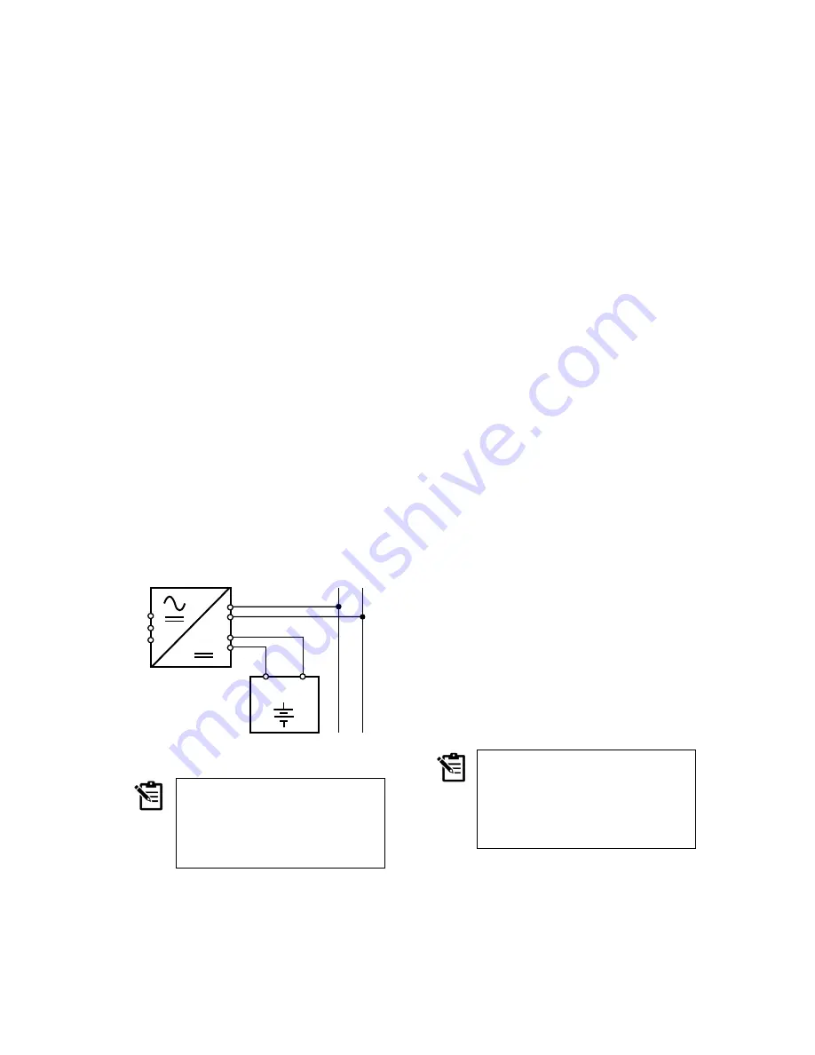
The standard configuration for all DC-
UPS units is as follows.
A DCU unit connected to mains, with
Battery output connected to a BBX unit
(or customer battery pack) and Load
output connected to the buffered DC
load via the DC BUS.
Figure 12.1 – Standard Output configuration
NOTE
Protect the Load output.
Design the load circuit to
prevent high reverse return
voltage (e.g., from a battery or
a decelerating motor).
12.2
Redundancy Output
configuration
Redundant power supply systems are
required in applications which demand
high reliability in operation. They require
multiple DC-UPS units connected in
parallel. As an example, 100%
redundancy means that in case of one of
the DC-UPS units becoming faulty, there will
be another one able to meet 100% of load
demand without interruption.
To do so, the DC-UPS units to be
connected in parallel must be large
enough to ensure that the total current
requirement of all buffered loads can be
fully met by one unit.
The DC-UPS units must be connected to the
DC bus through a Decoupling Diodes
module, like DCM20. See Figure 12.2.
Each DC-UPS is monitored by the Fault
LED on the front. The Fault relay contact
reports the alarm to a remote position or
logic controller
As an advantage, 100% redundancy enables
to hot-swap the failed DC-UPS and
replace it with a new one without system
down time.
12.3
Series Output
configuration
More DCU units of the same type can be
connected in series to provide higher
voltage rating, as shown in Figure 12.3.
However, please consider the following
note:
NOTE
In case of three-phase mains,
if possible, connect each DC-
UPS to different phases
Use separate primary-side
protection for each DC-UPS.
–
+
DC-BUS
–
+
–
+
N
/
–
L/
+
PE
BBX
BATTERY BOX
Summary of Contents for DCU150M1224S
Page 8: ...8 3 3 Dimensions Figure 3 2 Side and front views ...
Page 24: ...24 ...


