28
14
Technical Data
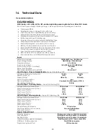
General description:
DCU150M1224
DCU Series - DC-UPS, AC to DC uninterruptable power systems for critical DC loads
All-in-One: Power Battery c Back-up functions, all packaged in one box.
Total power 150W
Selectable Output Voltage, 12 Vdc or 24 Vdc
Load-first, Dynamic Load/Battery power sharing
Adjustable maximum battery charging current
Suitable for backup of high inrush current DC loads
Buffer time setting of load backup
Universal charging output, selectable Battery Type
Temperature compensation sensor via USB port
Manual Battery start-up button with no mains
Battery life test, automatic or via manual button
Extensive
BATTSAFE
battery management firmware
Full set of protection and monitoring functions
Local monitoring and diagnostics on LEDs
Remote alarms via 3 voltage-free relay contacts
Communication via MODbus/CANbus data link
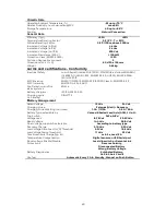
Input
Rated Input Voltage
115/230/277 Vac , 110/220 Vdc
Input Voltage Range
85–305 Vac , 110–420 Vdc
Frequency Range
47- 440 Hz
Input Current (Typ.)
1.6 A (115 Vac) , 0.6 A (230 Vac)
Inrush Current (Typ. Cold Start)
15 A max
Setup, Rise Time Max
1 s
RecommendedExternal Fuse/MCB
6 A, curve C
Load Output – Power Supply Mode
–
Mains ON & Battery OFF
Voltage, selectable by Dip Switch
1
12 Vdc
24 Vdc
Rated Current (I
R
)
10 A
5 A
Ripple / Noise
2
80 mV
pp
100 mV
pp
Short Circuit Protection
yes
Over Load Protection
Constant Current mode > 110% I
R
Over Voltage Protection
35 Vdc
Load Output – Standby Mode
–
Mains ON & Battery ON
Voltage Range, Automatic Set
1
12-14.4 Vdc
24-28.8 Vdc
Max Continuous Current (I
R
+I
BATT
)
15 A
10 A
Max Current for 30 s
17 A
15 A
Max Current for 15 s
20 A
20 A
Max Current for 5 s
< 25 A
< 25 A
Load Output – Backup Mode
–
Mains OFF & Battery ON
Voltage Range, Automatic Set
1
9.5-12 Vdc
18.5-24 Vdc
Max Continuous Current (I
R
+I
BATT
)
15 A
10 A
Max Current for 30 s
17 A
15 A
Max Current for 15 s
20 A
20 A
Max Current for 5 s
< 25 A
< 25 A
Time Buffering for Backup
30 s up to ∞
Start from battery with no mains
Yes, on Push Button
Quiescent current
< 90 mA
Signal Output/Input
Standby / Backup
Change-over relay contact, M terminals
Common Fault
Change-over relay contact, F terminals
Rectifier failure
Change-over relay contact, S terminals
Full set of monitor and alarm visual signals
Flashing code on 3, Three-color LEDs
MODbus / CANbus data link
Dual RJ45 connector
Programming Serial Port
USB connector
Summary of Contents for DCU150M1224S
Page 8: ...8 3 3 Dimensions Figure 3 2 Side and front views ...
Page 24: ...24 ...


