10
LINEARIS
4.5.2
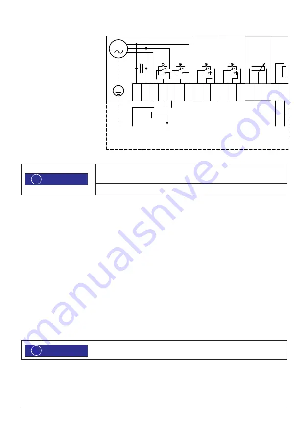
Wiring diagram
S1L
Limit switch, CCW
S2R
Limit switch, CW
S3
Auxiliary switch 1 (Option)
S4
Auxiliary switch 2 (Option)
S5
Auxiliary switch 3 (Option)
S6
Auxiliary switch 4 (Option)
R1
Potentiometer 1
R2
Potentiometer 2 (Option)
HZ Heating
M
Current output (Option)
K1
Relais for parallel operation
(Option)
All auxiliary switches must be operated within the same voltage range. Do not mix line
voltage with low voltage.
For options follow the wiring diagrams inside the actuator.
5.
Operation of the actuators
5.1
Set up rotation direction
Due to the internal wiring, the rotation direction (viewing direction is through the actuator towards the shaft) and the limit switches
assign as follows:
1. With line voltage on terminal 1 and 2, the actuator shaft rotates
counter-clockwise
and results in a pushing stroke.
Limitation of this stroke with lower switch S1L. When the switch is activated, line voltage is on terminal 4.
2. With line voltage on terminal 1 and 3, the actuator shaft rotates
clockwise
and results in a pulling stroke. Limitation of this
stroke with lower switch S2L. When the switch is activated, line voltage is on terminal 5.
3. If the actuator runs counterrotating to the commands, change the external connection of terminal 2 and 3 .
Depending on the model, limit switches may be arranged different than drawn in the wiring
diagram (see wiring diagram inside the actuator).
ADVICE
!
ADVICE
!
SP AC + 2ZW + P + Hz
1001.34
Datum:
31.03.2007
S4
S3
6 7 8 9 1011
R
1
18 19 20
H
Z
N L
27 28
1
N
M
S2R
S1L
2 3 4 5
C
B
A B
N
PE
L
Anschlussvariante
/ Alternative connection
L 0 R
AGS-Stellantriebe GmbH
Görlitzer Str. 2
D - 33758 Schloß Holte


