11
LINEARIS
S1L
S2R
S1L
S2R
S3
S4
S2R
CL-S
CL-M
CL-H
CL-L
S1L
CL-S
CL-M
CL-H
CL-L
Rechtslauf
CW run
Linkslauf
CCW run
JNO (2er)
Justierschrauben „J“
Adj. screw „J“
JNO (4er)
Justierschrauben „J“
Adj. screw „J“
5.2
Set up limit switches
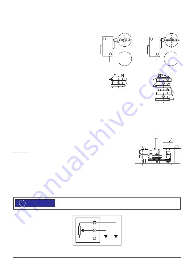
Depending on the model, the cams may be factory pre-adjusted to a switching position.
1. Apply voltage for CCW run (pushing stroke). The
actuator moves towards the preset direction.
2. Depending on the model, the shaft rotates with or
against the rotation direction of the lead screw. Switch
off voltage when the desired end position has reached
(avoid blocking of the gear!).
3. Turn the switch cam „S1L“ via the adjustment screw
„J“ in rotating direction of the shaft until the appropri-
ate switch „S1L“ clicks.
4. Check setup by moving the actuator again electrically
and adjust if necessary.
5. Adjust all other switches accordingly.
5.3
Optional modules and extra features
5.3.1
Potentiometer
Electrical connection
Connect terminals 18, 19 and 20 according to the desired requirements (voltage ≤ 50V); (see
page 10). Use only separate (shielded) wires.
Adjustment
Set up limit switch before adjusting the potentiometer P. Approach both end positions electrical-
ly (see chapter 5.2). Observe travel and potentiometer solution.
Do not overrun the ordered travel to avoid damage to the friction clutch R by permanent
override. Potentiometer P adjusts roughly automatically.
The travel of the valve is transferred to the rotating angle of the potentiometer by the friction clutch R. Approach both end positions
again electrically and adjust potentiometer P with the friction clutch R.
All potis must generally run under a potential divider circuit.
S1L
S2R
S1L
S2R
S3
S4
S2R
CL-S
CL-M
CL-H
CL-L
S1L
CL-S
CL-M
CL-H
CL-L
Rechtslauf
CW run
Linkslauf
CCW run
JNO (2er)
Justierschrauben „J“
Adj. screw „J“
JNO (4er)
Justierschrauben „J“
Adj. screw „J“
S2R
S1L
P
R
18
19
20
U+
U–
U
M
ADVICE
!


