background image

OPERATION AND OPERATOR INTERFACE

Main Operator Interface Screen

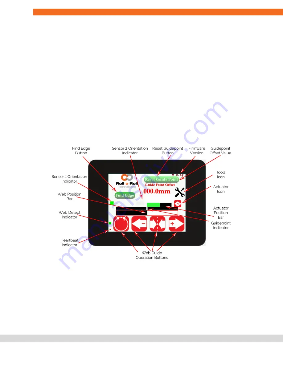
The main operator screen provides relevant information and operator access for both the sensing and
guiding application. The web guiding operations are accomplished using the web guide operation buttons on
the bottom of the screen.

The capacitive touchscreen on the SCU5 controller uses a language independent icon based screen that
allows ease of operation.

Never use sharp or pointed tools of any kind to operate the interface. Best practice is to have operators use
their fingers to press the different icons. Care must be taken to clean the touch screen surface periodically.

Its icon based design allows for a language independent operation without the need of translation of the
screen for setup and operation in different countries.

Heartbeat Indicator

A round indicator at the bottom left of the operator interface indicates the heartbeat or the communication
between the electronic controller board and the operator interface.

This indicator is used for troubleshooting purposes.

During normal operation this indicator will toggle between red and green at about 1 Hz.

NOTE:

Slow heartbeat may indicate communication delay between the main motherboard and the

touchscreen display/operator interface.

Content subject to change without notice

SCU5: Sensor and Web Guide Controller User Manual v 3.6| Page 15

Copyright © 2021 Roll-2-Roll Technologies LLC

https://r2r.tech

+1-888-290-3215

Summary of Contents for SCU5

Page 1: ...SCU5 Controller Product and User Manual Firmware Version 3 6 ...

Page 2: ... which it is disclosed Information in this document is believed to be reliable and accurate However no responsibility is assumed as a result of its use nor for any inaccuracies infringement of patent or other rights of third parties resulting from its use The information in this document is subject to change without any notice Content subject to change without notice SCU5 Sensor and Web Guide Cont...

Page 3: ...ort 3 13 SAFETY INSTRUCTIONS 14 Instructions for Use 14 Proper Use 14 Improper Use 14 Static Discharges and Grounding 14 OPERATION AND OPERATOR INTERFACE 15 Main Operator Interface Screen 15 Heartbeat Indicator 15 Web Detected Indicator 16 Web Position Indicator 16 Sensor Orientation Indicator 17 Find Edge Button 17 Automatically find the sensor orientation 17 Enable and disable the sensors 17 Aut...

Page 4: ...d Feature 28 Feature Navigation 28 Teaching 28 Contrast Mode 28 Right edge of a color 29 Edge created by two colors 30 Color of a line 30 Left Edge of a color 31 Operator Width Screen 32 Nominal Width 32 Upper Limit 33 Lower Limit 33 Measured Width 33 One Sensor 33 Two Sensors 33 Teaching 34 Output Type 34 Absolute 34 Error 35 Display Screen 35 Power User Screen 35 Actuator Setting 36 Stroke 36 Pi...

Page 5: ... 44 Subnet Mask and Gateway 44 MAC address 45 Module Type 45 Network IC Type 45 REMOTE CONTROL AND MONITORING 46 EtherNet IP Connection Parameters 46 PROFINET Connection Parameters 46 EtherCAT Connection Parameters 46 Controller Output and PLC Input 47 Sensor status and fault registers 47 Sensor 1 Sensor 2 Left Edge 49 Sensor 1 Sensor 2 Right Edge or Contrast 49 Sensor 1 Sensor 2 Coverage 50 Quali...

Page 6: ... Sensor 2 Brightness Override Value 57 Web guide command register 58 Guide point offset register 59 Actuator speed register 60 Actuator acceleration register 60 COMMISSIONING 61 Sensing and Measurement Application 61 Web Guiding Application 61 Edge Guiding 61 Center Guiding Application 62 Standard Operating Procedure 62 General Maintenance 62 TECHNICAL SUPPORT AND SERVICE 63 Contact information 63...

Page 7: ...as width measurement thread counting mark detection contrast position measurement gap detection and the like Web Guiding Application A web guiding system is a fully automatic mechatronic system used to accurately align steer web materials within roll to roll machines The web guide is used at critical locations where accurate alignment of web is necessary Typical locations include at the unwind sec...

Page 8: ...tion Sensor and Web Guide Controller Specification The general specifications of the SCU5 controller are listed below Depending on the application one of more of the output options would be available Operator Interface Color touchscreen Output Voltage 10 V or 0 to 10 V Languages Language independent Output Current 0 to 20 mA or 0 to 10 mA Motor Driver Microstepping or servo drive Connectivity Ethe...

Page 9: ...s Fault Info YES YES Process two sensors YES YES YES YES GO NO GO YES1 NO YES1 NO Standalone System YES YES5 YES YES5 1 Two digital 24 V NPN GO NO GO output are available upon request This is not a standard 2 can be programmed to be 10 V or 0 to 10 V or 5 V or 0 to 5 V based on application requirement 3 can be programmed to be 0 to 20 mA or 4 to 24 mA or 0 to 10 mA based on application requirement...

Page 10: ...t notice The SCU5 M controller has the following ports for connections to the sensor motor driver and other devices Fig 3 SCU5 MD Connector Ports Content subject to change without notice SCU5 Sensor and Web Guide Controller User Manual v 3 6 Page 9 Copyright 2021 Roll 2 Roll Technologies LLC https r2r tech 1 888 290 3215 ...

Page 11: ... as Mean Well SDR 75 24 can be used to supply 24VDC power This is an available purchase option Grounding For safety and for normal operation the SCU5 M controller the equipment to which the controller is installed must be properly grounded The metal enclosure surface or the mounting screws may be used to properly ground the controller to the protective earth WARNING Please use all possible options...

Page 12: ...les and sensors may damage the controller and will void the warranty Please consult with the factory before adding any patch cords Motor Communication Port 2 The SCU5 controller with M suffix includes a 4 pin Male M8 connector to connect the controller to a motor driver supplied by Roll 2 Roll Technologies LLC used for web guiding applications A pre wired motor communication cable with the 4 pin M...

Page 13: ...to power sensors Please do not connect the voltage source to these pins This might permanently damage the controller Industrial Ethernet Interface Port 3 An optional industrial ethernet connection is available on models with suffix C E or C P A 4 pin D coded M12 socket connect is provided for ethernet connection Standard network cables such as Phoenix Contact NBC MSD 1 0 93E R4AC SCO 1407360 or VS...

Page 14: ...VDC and GND from a PLC and the signal through the two outputs OUT1 and OUT2 Custom programing can be done to provide a GO NO GO type of output or a digital ON OFF signal When the respective output signal is enabled then that signal would go low And normally the signal would be high if wired as shown in the schematic on the left Note that the outputs are normally closed If wiring a relay wire to th...

Page 15: ...pment that process materials in web form as they move through a converting or raw material manufacturing process Improper Use Outdoor use or exposure to direct sunlight is considered improper Any use outside the general specifications shall be considered improper use and voids any warranty of the equipment Any replacement parts or modification necessities should be made by Roll 2 Roll Technologies...

Page 16: ...urface periodically Its icon based design allows for a language independent operation without the need of translation of the screen for setup and operation in different countries Heartbeat Indicator A round indicator at the bottom left of the operator interface indicates the heartbeat or the communication between the electronic controller board and the operator interface This indicator is used for...

Page 17: ...nsor range The edge position or the contrast position is displayed using the white horizontal bar The white portion indicates the web specifically representing the light reflected scattered back from a web while the black background indicates the absence of web specifically the darkness because of no reflection or scattering from the web Depending on the position and orientation of the sensor the ...

Page 18: ...t a predefined orientation pressing the find sensor button will successively enable and disable the connected sensors electronically Automatically find the sensor orientation The sensor orientation with respect to the web can be automatically detected in this mode when the find edge button is pressed This allows for quick job changes when the sensor is repositioned within the machine This is espec...

Page 19: ...ess upsets Caution must be exercised when changing the operating mode and should be done by those who completely understand the consequence of this change WARNING No personnel should be manually handling the web guide or the material around the web guide when the guide is in automatic operation Failure to follow this warning could result in crushing of body parts at pinch points around and within ...

Page 20: ...n the web guiding system is in manual mode Pressing the servo center icon during automatic operation will perform a different function WARNING This is an automatic procedure of the web guiding system No personnel should be performing manual work on or around the guide during the servo centering procedure Failure to follow this warning could result in crushing of body parts at pinch points around a...

Page 21: ... the guide point and the actual web position will drive the actuator inorder to minimize the error Typically the guide point is set to the exact middle of the sensor window range However the guide point can be changed electronically to any location within the sensing window Guide Point Indicator The guide point indicator which is on top of the web position indicator provides a visual indication of...

Page 22: ...ppears whenever the track bar is moved The confirmation is intended to prevent any accidental changes to the guide point If the guide point change is not accepted within 10 seconds the change will be disregarded and the previously accepted guide point will be restored NOTE The pressing of the Left or Right during fine guide point adjustment will momentarily change the icon to green With the releas...

Page 23: ...ll be disregarded and the previously accepted guide point will be restored NOTE This functionality has no meaning for sensing application However some custom applications with custom firmware may use the functionality Actuator Position Bar The actuator position bar provides a real time electronic position of the actuator The extension and retraction of the actuator is shown by the movement of the ...

Page 24: ...ar is choppy or intermittent this indicates some communication issues between the SCU5 controller and Roll 2 Roll Driver WARNING If the actuator connected to the SCU5 moves but the actuator position bar does not indicate any movement either completely black or red this might be due to corrupted electronic position of the actuator in the memory This is not normal and should be addressed immediately...

Page 25: ...sed for access to the operator screen and the power user maintenance screen The factory access is only available to Roll 2 Roll Technologies personnel By default the password protection will be disabled and both the operator icon and the power user icon are visible to the user If password protection is enabled the two icons would disappear The keypad can be used to type the appropriate password to...

Page 26: ...edge sensing mode When the icon is black green and white then the controller operates in contrast mode NOTE If two sensors are connected to a single controller the controller will process both the sensors with a single mode of operation In other words the two sensors cannot have different modes of operation Thresholding Mode Thresholding mode can be set to either static or dynamic For most applica...

Page 27: ...Content subject to change without notice SCU5 Sensor and Web Guide Controller User Manual v 3 6 Page 26 Copyright 2021 Roll 2 Roll Technologies LLC https r2r tech 1 888 290 3215 ...

Page 28: ...ller is taught to track a certain feature on the web WARNING If the sensing mode is contrast and if the minimum contrast value is too low or zero then the contrast detection algorithm will not function properly and would perceive every small change in the image For contrast mode the recommended default value is 50 WARNING If the sensing mode is edge and if the minimum contrast value is too low or ...

Page 29: ...ow keys can be used to scroll through the live processed image preview to select the appropriate contrasting feature of interest Depending on the contrast mode chosen the arrow keys will move the edge or the line to the left or to the right NOTE The feature selection key can be used only when the controller is in teaching mode Teaching When the controller is in teaching mode the gear icon will app...

Page 30: ...s mode the controller will look for the right edge of a certain color or grayscale as shown below A three sided open rectangle will highlight the region of interest with the right edge of the color region highlighted in green The user can press the feature navigation arrows to navigate to the region of interest When the desired region of interest is highlighted the teaching can be saved by pressin...

Page 31: ...aching Saved NOTE The Order of the colors matters in this mode In the above example if the sensor is taught from gray followed by black and if the order is reversed to black followed by gray if the sensor is rotated 180 the controller will not pick that edge even though the two color regions are the same NOTE If multiple regions have the same color pair such as in a barcode the controller will alw...

Page 32: ...on of interest and the left edge of that region will highlight the region Once the desired region is selected the teaching can be saved by pressing the gear icon If the saving is successful all other modes will disappear and the gear icon would turn red Left edge of a color Teaching Left edge of a color Teaching Saved NOTE While teaching the controller will not scroll through a region without a pr...

Page 33: ...means no contrast condition Operator Width Screen For width measurement applications the operators can set the job by navigating to the width menu on the operator settings screen If one sensor is used for width measurement the controller should be in edge mode with sensor configuration to be in center sensor If two sensors are used to measure web width then the sensor should have the corresponding...

Page 34: ...l time width value based on the image captured by one or two sensors The measured width is the sum of raw measurement from each sensor plus any offset Offset is often necessary when the width is measured with two sensors Since the controller does not know the actual distance between the two sensors the offset is necessary to compute the measured width based on the raw width measurement from the se...

Page 35: ...will calculate the offset If the nominal width is different from the known width used for teaching then the appropriate nominal width can be reset NOTE When the teaching wand is pressed the controller will compute the offset using this equation offset nominal width raw measurement from the sensor s The offset is not shown on the display however the measurement width will be shown Since the measure...

Page 36: ...agnitude of voltage change on the analog output would not change based on the sensor range For example if the error is 2 mm irrespective of the sensor range the analog output would always be NOTE The analog output setting which can be set as shown in the following sections should be set to width inorder for the width measurement to function properly NOTE It is intuitive to see the output when the ...

Page 37: ...ecremented using the and keys This digital stoke setting is used to keep track of the distance the actuator can move on either side from the servo centered position Hence from the middle position servo centered position the actuator will travel half the stroke length on either side This digital stroke length setting helps prevent the actuator from hitting the mechanical limits and prevent any moto...

Page 38: ...f the desired correction when in automatic mode This is an immediate indication of the incorrect setting Servo Center Polarity The polarity of the servo center can also be changed in order to accommodate various locations for the sensor installation This may be necessary if the location of the servo center is changed or if a different type of servo center sensor is used WARNING If the servo center...

Page 39: ...ing the brightness too high would disable the background suppression algorithm so this should be carried out only by the power user who is knowledgeable and aware of its consequences WARNING Manually setting the brightness too low may prevent the controller from seeing the web Never set the brightness to zero without consulting the factory about the application NOTE If the sensor mode is set to co...

Page 40: ... the user may prefer to manually set the state of the sensor to Left Right or Center In edge sensing mode the sensor will look for the web edge scanning from the outside to the inside of the sensor For a left sensor the scan goes from left to right while for a right sensor the scan goes from right to left A center sensor state is one in which both the edges of a web are within the field of view of...

Page 41: ...This parameter may affect the stability of the overall web guiding system and hence should be changed with care Deadband Deadband is the region around the guidepoint where the actuator will not be actuated if the web is within this deadband This integer value is in pixels and by default the deadband value is 4 pixels or 0 25 mm With that setting the actuator will not move if the web is within 4 pi...

Page 42: ...nsor since the sensor will reset recalibrate the position tracking of the controller WARNING If an external servo center sensor is enabled but no servo center sensor is installed the actuator will still move until the physical limit is reached This might cause the actuator to hit against its mechanical limit and can cause damage to the actuator However the controller will automatically recognize t...

Page 43: ...ting Output range selection The analog output setting can be changed based on the application The voltage ranges and the current ranges can be set by picking the appropriate selection The available voltage options are 0 to 5 V 0 to 10 V 5 V and 10 V The available current options are 0 to 10 mA 0 to 20 mA 0 to 24 mA and 4 24 mA NOTE Any combination of the voltage and current setting can be selected...

Page 44: ...ssword protected for both the power user screen access and operator sensor screen access Pressing the button will toggle the password enable disable option When the locked icon is displayed the password for the respective screen will be enabled NOTE Please contact the factory for the passwords for the respective screens NOTE The passwords for the respective screens cannot be changed However if a c...

Page 45: ... as the IP address Same rules for setting these parameters are applicable NOTE Changing the IP address subnet mask and or gateway requires the controller to be power cycled NOTE If any of the 3 digits is more than 255 the digits do not correspond to a valid 8 bit number The whole address would be reset to zero and the user would have to start entering the numbers again NOTE Entering a valid 8 bit ...

Page 46: ...y the type of network IC installed The two options are HMS and Hilscher If the correct network IC is not initialized then it will appear as none NOTE If all of the address fields and the mac address is zero then the ethernet module is not initialized Make sure to turn ON ethernet and power cycle the controller If the problem persists you may not have an ethernet module on your controller or the et...

Page 47: ...dule as a generic EtherNet IP module in the PLC Assembly Instance Size Bit Input 100 16 16 bit Output 150 8 16 bit Configuration 1 0 8 bit PROFINET Connection Parameters Ethernet module configuration value based on the PROFINET GSDML file Input Module 100 32 Bytes Output Module 150 16 Bytes NOTE For PROFINET systems the 16 bit data from the controller are split into two bytes and byte swapped The ...

Page 48: ...offset 11 Motor Speed Percentage Motor Acceleration Percentage 12 Sensor 1 Thread Count 13 Sensor 2 Thread Count 14 Sensor 1 Mean Width or Total Web Width 15 Sensor 2 Mean Width or Total Web Width Sensor status and fault registers The sensor status fault register is organized as follows The eight least significant bits correspond to fault information while the eight most significant bits correspon...

Page 49: ... the web 6 NA Reserved for future use 7 0 1 WPS or ODC 0 WPS Sensor 1 ODC 8 0 1 Left Sensor 0 if the sensor not set as a left sensor 1 if the sensor is set as a left sensor 9 0 1 Right Sensor 0 if the sensor not set as a right sensor 1 if the sensor is set as a right sensor 10 13 1 15 Number of pixels The number of pixels in the sensor and the corresponding sensor resolution When bit 7 is zero 0 2...

Page 50: ...de is edge then this register will provide the left edge of the web Note If the sensor orientation is set to the right sensor then this value would be zero Note If the sensor orientation is set to the right sensor or if the sensor mode is contrast then this value would be meaningless Sensor 1 Sensor 2 Right Edge or Contrast If sensing mode is edge then this register will provide the right edge of ...

Page 51: ...m of individual widths Note When only one web with both edges within the sensor field of view is presented to the sensor the coverage value will be the same as the web width The coverage value is computed based on edges seen by the controller Hence based on the controller settings if multiple contrasting features on the web are seen then coverage value will not be the same as the web width Note Th...

Page 52: ...5 0 1 Upstream misalignment 0 if no upstream misalignment is detected 1 if an upstream misalignment is detected 6 0 1 Guide extreme position 0 if the web guide is within the normal position 1 if the web guide is in an extreme position 7 0 1 High frequency disturbance detected 0 if a high frequency disturbance is detected 1 if no high frequency disturbances are detected 8 0 1 Manual Auto 0 if the w...

Page 53: ...anges between 0 and 100 Actuator acceleration percentage The acceleration of the actuator as a percentage of maximum acceleration is provided in the least significant bits of register 7 The value ranges between 0 and 100 Sensor 1 Thread Count When multiple webs or strings or threads are viewed by the sensor the number or the count of threads is provided in the register Sensor 2 Thread Count When m...

Page 54: ...U5 Note If the filter is enabled the output provided would be the filtered output When the SCU5 controller is not set to provide width then the registers provide the mean widths of the webs seen by each sensor Register 14 will provide the mean width of the webs seen by sensor 1 and register 15 will provide the mean width of the webs seen by sensor 2 Note The mean width is computed by adding all th...

Page 55: ... Sensing mode 0 set the sensing mode to be edge mode 1 set the sensing mode to be contrast mode 3 5 0 7 Analog mode 0 Analog output is disabled 1 Analog output is enabled and zero scale voltage current is output Note This mode can be used during calibration while connecting the controller to a third party controller that requires calibration During the calibration this mode can be selected to cali...

Page 56: ... output The coverage is the percentage of the sensor covered by web s This is used when webs can have gaps or voids in them Unlike width output which takes the leftmost edge and the rightmost edge the coverage will not include the gaps void between the leftmost edge and the rightmost edge Note There is only one analog output while two sensors can be connected to the controller Please be aware that...

Page 57: ...ration the brightness of the individual sensors are allowed to vary from 4 to 100 However power users can change that limit through ethernet by setting this bit and writing values to the two remaining 7 bit registers Maximum and Minimum Brightness Limit The maximum value for the brightness of the LEDs can be written to bits 13 7 while the minimum value can be written to bits 6 to 0 Note These maxi...

Page 58: ...s a remote brightness override functionality When these bits are set the user can remotely set the brightness by writing a 6 bit value to the corresponding sensor Sensor 1 Sensor 2 Brightness Override Value The brightness of Sensor 1 and Sensor 2 can be changed remotely by writing a value between 0 to 64 in these two 6 bit registers The corresponding brightness override bit has to be set before th...

Page 59: ...is momentary Before decreasing the guidepoint the bit needs to be cleared before setting it to one Note that the guide point cannot be at the extremes of the sensing window and will automatically truncate if the extreme limit is reached The extreme limit depends on the sensor resolution and sensor width 11 0 1 Jog Right or increase guidepoint This bit performs two functions based on bit 9 If bit 9...

Page 60: ...aution must be exercised when performing these functions and should be done by those who completely understand the consequence of this change WARNING Web Guiding System enabled by SCU5 controller is an automatic control device that may stop and start at any time without notice especially when controlled remotely Hence standard safeguards must be in place to prevent any kind of injury WARNING The r...

Page 61: ...icant bits will be ignored Actuator acceleration register The acceleration of the actuator can be changed by setting the 7th bit of the register to 1 and writing a value between 0 and 100 in the 7 least significant bits If the 7th bit is low then the value written in the register is being ignored Content subject to change without notice SCU5 Sensor and Web Guide Controller User Manual v 3 6 Page 6...

Page 62: ...anual icon pressed to red 3 Press the Servo Center button to center the guide rollers 4 Thread the material over the rollers The material wrapped over the rollers must be at a 90 degree angle both at the entry and exit of the guide rollers 5 Verify that the material is aligned in the desired position with respect to the upstream and downstream position of the web Place the web under normal operati...

Page 63: ... the new location of the web is still within the sensing window of the sensor 6 If the web is guided to the center line position reset the guide point to the current location of the web while ensuring that both edges are seen by the sensors 7 Set the web guide in automatic mode 8 If during operation fine adjustments to the guide point are needed then use the fine guide point adjustment procedure t...

Page 64: ...Phone 1 888 290 3215 ext 3 General Support Phone 1 888 290 3125 ext 1 Technical Support Email engineering r2r tech General Support Email support r2r tech Return shipping instructions Please contact us to obtain a return merchandise authorization RMA number before returning the product to us If returning the product please follow the instructions on the RMA form for quick and efficient service Cont...

Page 65: ...RTCC SCU V4 Rev C Mar 2016 Analog Output SCU V4 Rev D July 2016 Industrial ethernet option SCU5 Rev B May 2017 Smaller form factor board SCU5 Rev C Nov 2017 Robustness improvements SCU5 Rev D Dec 2018 Added Digital output option Content subject to change without notice SCU5 Sensor and Web Guide Controller User Manual v 3 6 Page 64 Copyright 2021 Roll 2 Roll Technologies LLC https r2r tech 1 888 29...

Page 66: ... for power users 3 3 Dec 2018 Updated functionality to version 3 algorithm 3 3c Jan 2019 Updated functionality to include minimum contrast setting 3 3d Jun 2019 Added functionality for both static and dynamic thresholding 3 4 Jul 2019 Significant update with added functionality for power user access and for built in width measurement application 3 4a Aug 2019 Added the ability to view and change t...

Page 67: ... Dr Stillwater OK 74074 www r2r tech com info r2r tech com 1 888 290 3215 Content subject to change without notice SCU5 Sensor and Web Guide Controller User Manual v 3 6 Page 66 Copyright 2021 Roll 2 Roll Technologies LLC https r2r tech 1 888 290 3215 ...

Reviews: