Chapter 4
Cabling the Switch
The following topics are covered in this section:
•
•
•
Connecting Serial and Management Cables
4.1
Grounding the Switch
After mounting the switch into the rack, connect the switch to the data center ground.
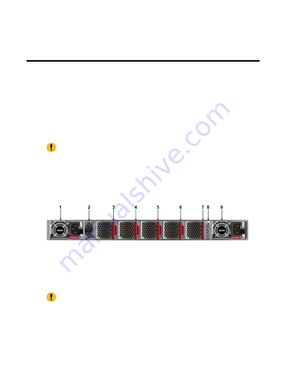
displays the location of the grounding pads located on the rear panel
of the
switches.
Important:
Grounding wires and grounding lugs (M4 x 0.7) are not supplied. Wire size should meet local
and national installation requirements. Commercially available 12 AWG wire is recommended
for installations in the U.S.
À la terre et de mise à la terre fils cosses (M4 x 0.7) ne sont pas fournis. Calibre des fils doit
satisfaire des exigences de l’installation locale et nationale. Disponible dans le commerce 6 fils
AWG est recommandé pour les installations aux États-Unis.
Figure 14: Earth Grounding Pad Sockets
1 Power Supply Module 1
4 Fan Module 2
7 Fan Module 5
2 Management Ports
5 Fan Module 3
8 Ground
3 Fan Module 1
6 Fan Module 4
9 Power Supply Module 2
4.2
Connecting Power Cables
Important:
Installation of this equipment must comply with local and national electrical codes. If
necessary,
consult with the appropriate regulatory agencies and inspection authorities to
ensure
compliance.
Installation de cet équipement doit être conformes aux codes électriques locaux et nationaux.
Si nécessaire, consulter les organismes de réglementation appropriés et des autorités de
contrôle pour assurer la conformité.
17


