34
Quick Start Guide: 7368x Series Modular Data Center Switches
Power Supplies
Appendix F: Maintenance and Field Replacement
F.1.2
Inserting Switch Card Module
The module insertion process is the inverse of the removal procedure. Follow the steps listed below to
insert the switch card module into a chassis.
Step 1
Align the switch card module with the rails in the chassis for insertion.
Step 2
Slide the module gently into the chassis until you feel a little resistance towards the end. The
switch card module will extend just a little bit outside the chassis.
Step 3
Pinch the release levers towards the center and continue to push the module in until it is flush
with the chassis and let go of the release levers.
Step 4
Try moving the module out gently, without engaging the release levers. The module will not
move if it is seated correctly.
Step 5
Return the release handle to its locked position (up).
Note
Descriptions for the removal and replacement of power supplies and fans are for a representative
power supply or fan. Locations of status indicator LEDs may differ. Refer to the front and rear panel
illustrations of your device to locate the appropriate LED.
F.2
Power Supplies
The power supplies are accessible from the rear of the switch as shown in
. Refer to
for more details on the removal and replacement of a power supply unit.
The following steps are required when removing power supplies from a switch.
F.2.1
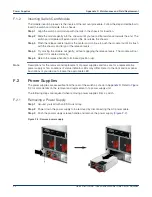
Removing a Power Supply
Step 1
Ground yourself with an ESD wrist strap.
Step 2
Power down the power supply to be removed by disconnecting the AC power cable.
Step 3
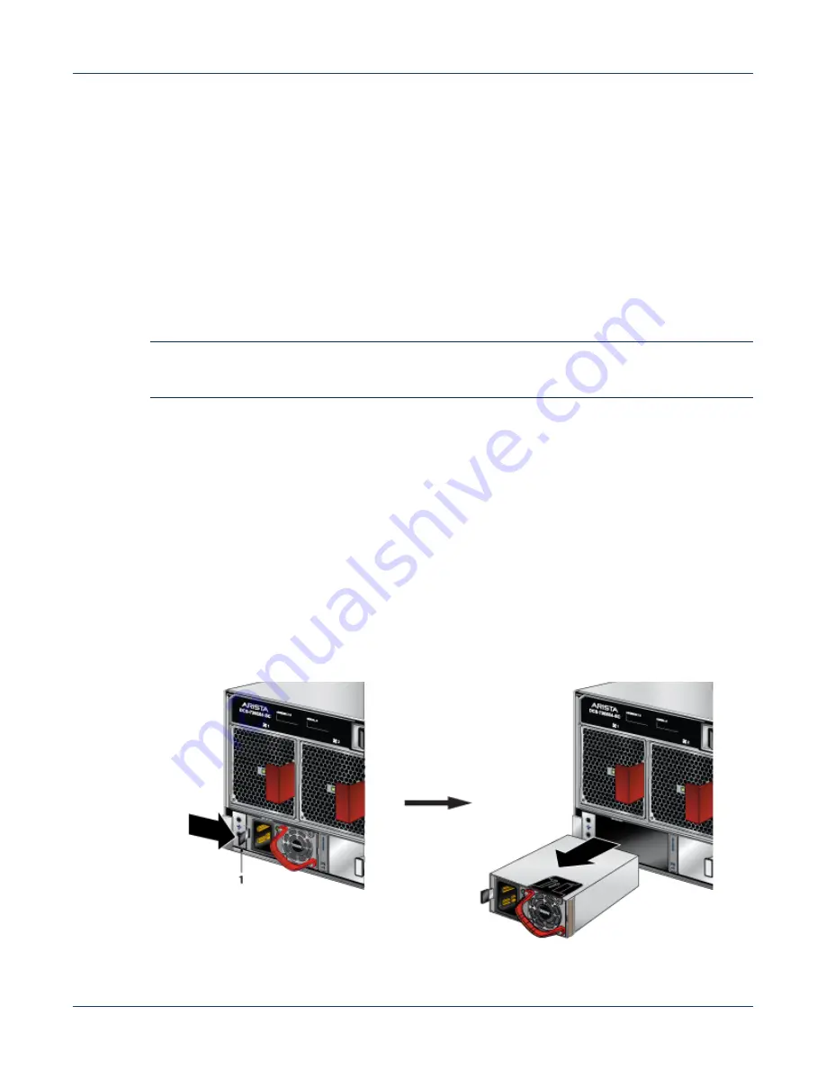
Push the power supply release handle and remove the power supply (
Figure F-2: Remove power supply
Summary of Contents for 7368X Series
Page 32: ...28 Quick Start Guide 7368x Series Modular Data Center Switches Appendix C Front Panels ...
Page 34: ...30 Quick Start Guide 7368x Series Modular Data Center Switches Appendix D Rear Panels ...
Page 36: ...32 Quick Start Guide 7368x Series Modular Data Center Switches Appendix E Line Cards ...


