Appendix F: Maintenance and Field Replacement
Fan Modules
Quick Start Guide: 7368x Series Modular Data Center Switches
35
F.2.2
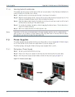
Installing a Power Supply
You must make space for installing the power supply by removing an existing one (
).
Step 1
Remove the replacement power supply from its packaging.
Step 2
Slide the new power supply into the empty slot.
Step 3
Slide the new power supply into the switch until the power supply is fully seated and the
release handle snaps into place.
Step 4
Connect the power cord to the power supply.
Step 5
Verify the LED(s) on the power supply.
Note
The Power Supply status LED should be a steady green for normal operation.
Step 6
Verify the new power supply operation by issuing the
show environment power
command.
switch#show environment power
The output of the command will list the power supplies in operation and should include the one you
replaced.
F.3
Fan Modules
The fan modules are accessible from the rear of the switch as shown in
. Refer to
for more details on the removal and replacement of a fan module.
F.3.1
Removing a Fan Module
The following steps are required when removing or replacing fans from a switch.
Step 1
Ground yourself with an ESD wrist strap.
Step 2
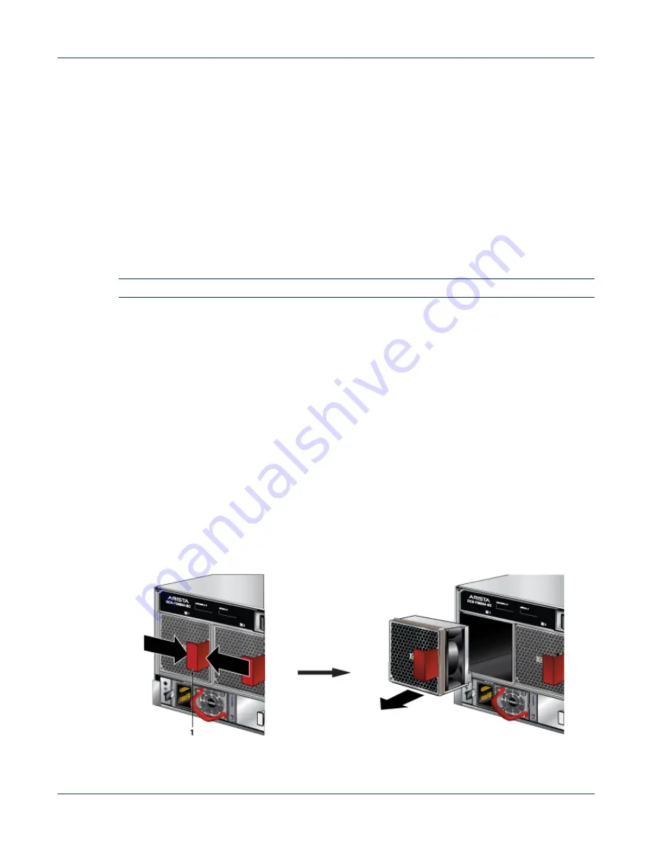
Push the fan module release lever and slide the fan module out of the switch (
Figure F-3: Removing fan module
1
PSU Release Handle
Summary of Contents for 7368X Series
Page 32: ...28 Quick Start Guide 7368x Series Modular Data Center Switches Appendix C Front Panels ...
Page 34: ...30 Quick Start Guide 7368x Series Modular Data Center Switches Appendix D Rear Panels ...
Page 36: ...32 Quick Start Guide 7368x Series Modular Data Center Switches Appendix E Line Cards ...

