background image


Arista ARP-2200AP User Manual


|


P a g e


Follow these simple precautions to protect yourself from harm and the products from damage. 


To  avoid  electrical  shock,  always  disconnect  the  power  from  the  PC  chassis  before  working  on  it.  Don’t  touch  any 

components on the CPU card or other cards while the PC is on. 


Disconnect  power  before  making  any  configuration  changes.  The  sudden  rush  of  power  while  connecting  a  jumper  or 

installing a card may damage sensitive electronic components. 


Summary of Contents for ARP-2200AP SERIES

Page 1: ...USER MANUAL ...

Page 2: ...reliable However Arista assumes no responsibility for its use nor for any infringements of the rights of third parties which may result from its use Acknowledgements VIA is a trademark of VIA Technologies Inc IBM PC AT PS 2 and VGA are trademarks of International Business Machines Corp Intel and Pentium are trademarks of Intel Corporation Microsoft Windows is a registered trademark of Microsoft Co...

Page 3: ...sed etc Note anything abnormal and list any onscreen messages when the problem occurs 2 Call your dealer and describe the problem Please have the manual product and any helpful information readily available 3 If the product is diagnosed as defective obtain an RMA return merchandize authorization number from the dealer This allows Arista to process the return more quickly 4 Carefully pack the defec...

Page 4: ...ings Cautions and Notes Sl No Symbols Descriptions 1 Warning Warnings indicate conditions which if not observed can cause personal injury 2 Caution Cautions are included to help you avoid damaging hardware or losing data Ex There is a danger of a new battery exploding if it is incorrectly installed Do not attempt to recharge force open or heat the battery Replace the battery only with the same or ...

Page 5: ...ive or Arista s customer service center for technical support and additional assistance Please have the following information ready before calling Product name and serial number Description of peripheral attachments Description of software operating system version application software etc A complete description of the problem The exact wording of any error messages Contact information Arista US Re...

Page 6: ...hat the items listed below are included and in good condition If any item does not accord with the table please contact your dealer immediately Sl No Revision By Approved By Revision History Revision Date 1 Navan Paul Shu ARP 2200 Series Users Manual Initial Draft Version 4 21 2010 2 3 4 5 6 7 ...

Page 7: ...quid has penetrated into the equipment The equipment has been exposed to moisture The equipment does not work well or you cannot get it to work according to the user s manual The equipment has been dropped and damaged The equipment has obvious signs of breakage 15 DO NOT LEAVE THIS EQUIPMENT IN AN ENVIRONMENT WHERE THE STORAGE TEMPERATURE MAY GO BELOW 20 C 4 F OR ABOVE 60 C 140 F THIS COULD DAMAGE...

Page 8: ...oid electrical shock always disconnect the power from the PC chassis before working on it Don t touch any components on the CPU card or other cards while the PC is on Disconnect power before making any configuration changes The sudden rush of power while connecting a jumper or installing a card may damage sensitive electronic components ...

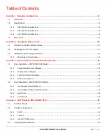
Page 9: ...ting on Panel Cutout 23 CHAPTER 3 DRIVER INSTALLATION FOR WINDOWS XP PRO 28 3 1 Driver Installation ARP2200AP A00 Model 28 3 1 1 Chipset Device Driver Software 28 3 1 2 Display Driver Software 31 3 1 3 Sound Card Driver Software 34 3 1 4 LAN Driver Software 36 3 2 Driver Installation ARP2200AP D00 Model 41 3 2 1 Intel Chipset Device Software 41 3 2 2 Intel Graphic Media Accelerator Driver 44 3 2 3...

Page 10: ...TS 69 6 1 USB Port 69 6 2 COM Ports 69 6 2 1 COM1 Serial Port 69 6 2 2 COM2 Serial Port 69 6 2 3 COM3 Serial Port 70 6 2 4 COM4 Serial Port 70 6 2 5 COM5 Serial Port 71 6 2 6 COM6 Serial Port 71 6 3 Ethernet 72 6 4 VGA Port 72 6 5 PS 2 Mouse and Keyboard 73 6 6 Touchscreen 74 6 7 Mounting Bracket 74 6 8 Audio 74 CHAPTER 7 VIDEO ALIGNMENT CALIBRATION 76 7 1 Options to Launch 76 7 2 Running the Alig...

Page 11: ...ttery 81 8 3 FCC Statement 82 8 4 Exclusion of Accident Liability Obligation 82 8 5 Liability Limitation Exemption from Warranty Obligation 82 8 6 Reinstalling the Operating System 82 8 6 1 Reinstalling the Drivers 82 8 7 Troubleshooting 82 CHAPTER 9 CERTIFICATES AND COMPLIANCE 84 ...

Page 12: ...Arista ARP 2200AP User Manual 12 P a g e Chapter 1 General Information General Information This chapter gives background information on the ARP 5500AX Series Sections include Specifications Dimensions ...

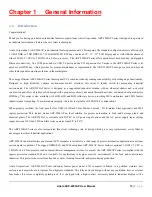
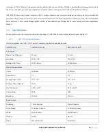
Page 13: ... drives providing 100 motionless and 100 fanless industrial panel computing To maintain data integrity the series is available with RAID 0 1 configurations When properly installed the front panels offer NEMA 4 Black Color Powder Coated 4X Stainless Steel optional and IP65 ingress protection This feature makes ARP 2200AP an ideal solution for process automation in food and beverage plants and chemi...

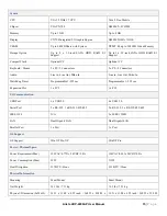
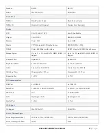
Page 14: ...mage 1 2 Specifications The section describes the complete specification and ratings of ARP 2200AP Series fanless industrial panel display PC 1 2 1 ARP 2215AP Specifications The following table lists ARP 2215AP model s complete specification and rating details ARP 2215AP ARP 2215AP A00 ARP 2215AP D00 LCD Panel Display Size Diagonal 15 inch 15 inch Resolution 1024 x 768 1024 x 768 Backlight Life Ti...

Page 15: ... Watchdog Timer Programmable 1 255 sec Programmable 1 255 sec Expansion Slot 1 x PCI 1 x PCI I O Communication USB Port 6 x USB 2 0 6 x USB 2 0 Serial Port 5 x RS 232 1 x RS 232 422 485 5 x RS 232 1 x RS 232 422 485 IEEE 1394 N A 2 x IEEE 1394B LAN Dual Gigabit LAN Dual Gigabit LAN Parallel Port 1 x Port 1 x Port OS Support OS Support Win XP Pro XP Win XP Pro Power Thermal Specs Power Requirement ...

Page 16: ...he following table lists ARP 2217AP model s complete specification and rating details ARP 2217AP ARP 2217AP A00 ARP 2217AP D00 LCD Panel Display Size Diagonal 17 inch 17 inch Resolution 1280 x 1024 1280 x 1024 Backlight Life Time 50 000 Hours 50 000 Hours Visual Characteristics Colors 16 Million 16 Million Aspect Ratio 4 3 4 3 Viewing Angle V H 1400 1400 1400 1400 Response Time Typical 12 ms 12 ms...

Page 17: ...HDD RAID 0 1 Support Up to 2 x 2 5 inch SATA HDD RAID 0 1 Support Compact Flash Optional CF Optional CF Keyboard Mouse 2 x PS 2 Connectors 2 x PS 2 Connectors Audio Line in Line Out MIC In Line in Line Out MIC In Watchdog Timer Programmable 1 255 sec Programmable 1 255 sec Expansion Slot 1 x PCI 1 x PCI I O Communication USB Port 6 x USB 2 0 6 x USB 2 0 Serial Port 5 x RS 232 1 x RS 232 422 485 5 ...

Page 18: ...e Temperature 200 600 C 40 1400 F 200 600 C 40 1400 F Relative Humidity 0 95 Non Condensing 0 95 Non Condensing Rating NEMA 4 4X Bezel NEMA 4 4X Bezel Certification 1 2 3 ARP 2219AP Specifications The following table lists ARP 2219AP model s complete specification and rating details ARP 2219AP ARP 2219AP A00 ARP 2219AP D00 LCD Panel Display Size Diagonal 19 inch 19 inch Resolution 1280 x 1024 1280...

Page 19: ...ated S3 Graphic Engine GME965 GMA x 3100 VRAM Up to 64 MB Share with system DVMT 4 0 up to 384 MB Video Memory Storage Option Up to 2 x 2 5 inch SATA HDD RAID 0 1 Support Up to 2 x 2 5 inch SATA HDD RAID 0 1 Support Compact Flash Optional CF Optional CF Keyboard Mouse 2 x PS 2 Connectors 2 x PS 2 Connectors Audio Line in Line Out MIC In Line in Line Out MIC In Watchdog Timer Programmable 1 255 sec...

Page 20: ...H 17 8 x 14 6 x 4 86 inch 452 12 x 370 84 x 123 50 mm 17 8 x 14 6 x 4 86 inch 452 12 x 370 84 x 123 50 mm Cutout Dimension LxW 16 90 x 13 70 inch 429 20 x 347 92 mm 16 90 x 13 70 inch 429 20 x 347 92 mm Environmental Operating Temperature 00 500 C 320 1220 F 00 500 C 320 1220 F Storage Temperature 200 600 C 40 1400 F 200 600 C 40 1400 F Relative Humidity 0 95 Non Condensing 0 95 Non Condensing Rat...

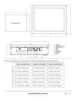
Page 21: ... BP CP DP A 11 80 inch 298 82 mm 13 34 inch 338 84 mm 14 6 inch 370 84 mm B 14 51 inch 368 55 mm 15 88 inch 403 35 mm 17 8 inch 452 12 mm C 13 65 inch 346 65 mm 14 97 inch 380 19 mm 16 90 inch 429 20 mm D 11 02 inch 279 82 mm 12 43 inch 315 67 mm 13 70 inch 347 92 mm E 4 52 inch 114 86 mm 4 86 inch 123 50 mm 4 86 inch 123 50 mm F 13 52953 inch 343 65mm 14 85 inch 377 19 mm 16 77953 inch 426 2 mm ...

Page 22: ...ual 22 P a g e Chapter 2 Hardware Installation Hardware Installation This chapter gives the hardware installation information for the ARP 5500AX Series Sections include A Quick Tour Installation Procedures Installing the Drivers ...

Page 23: ...Mounting Procedures The ARP 2200AP Series can be either panel or VESA mounted If utilizing a panel mount the chassis offers 12 mounting screw locations yielding NEMA sealability when properly installed If mounting on an arm or desktop mount the rear of the unit offers an industry standard 100mm VESA screw pattern Arista offers an optional adjustable ergonomic VESA mount to simplify desktop install...

Page 24: ...Arista ARP 2200AP User Manual 24 P a g e 2 Mount the key ways in base chassis of the unit 3 Assemble the Hanger Key 1 at 9 places and Hanger Key 2 at 4 places ...

Page 25: ...Arista ARP 2200AP User Manual 25 P a g e 4 Assemble the screw at 13 places in the unit 5 The following picture shows the IO communication ...

Page 26: ...Arista ARP 2200AP User Manual 26 P a g e ...

Page 27: ...a g e Chapter 3 Driver Installation for Windows XP Pro Driver Installation for Windows XP Pro This chapter gives information on installing drivers for Windows XP Pro operating system Sections include Driver Installation Updating Drivers ...

Page 28: ...ically Select the corresponding driver of utility CD if the install menu does not list the suitable drivers The ARP 2200AP A00 model refers to the VIA 1 5 GHz C7 CPU and E4215 motherboard Follow the instructions provided in the subsequent chapters to complete the driver installations 3 1 1 Chipset Device Driver Software This section describes the chipset device driver software installation procedu...

Page 29: ...Arista ARP 2200AP User Manual 29 P a g e 4 Click Next The update or remove program option appears ...

Page 30: ...al 30 P a g e 5 Select Update and click Next to proceed This displays the Install List items 6 Select the appropriate components to install and click Next This displays the current settings 7 Click Finish to complete the settings ...

Page 31: ...l 31 P a g e 3 1 2 Display Driver Software This section describes the display driver software installation procedures Follow these steps 1 Insert the utility CD to CD ROM to initiate the installation process 2 Click Display Driver ...

Page 32: ...Arista ARP 2200AP User Manual 32 P a g e 3 Double click Setup to continue ...

Page 33: ...Arista ARP 2200AP User Manual 33 P a g e 4 Click Finish to complete the setup ...

Page 34: ...d Card Driver Software This section describes the sound card driver software installation procedures Follow these steps 1 Insert the utility CD to CD ROM to initiate the installation process 2 Click Sound Card 3 Double click Win2KXP_WDM_A300 to continue ...

Page 35: ...Arista ARP 2200AP User Manual 35 P a g e 4 Click Finish to complete the setup ...

Page 36: ...ser Manual 36 P a g e 3 1 4 LAN Driver Software This section describes the LAN driver software installation procedures Follow these steps 1 Insert the utility CD to CD ROM to initiate the installation process 2 Click LAN ...

Page 37: ...Arista ARP 2200AP User Manual 37 P a g e 3 Double click Setup ...

Page 38: ...Arista ARP 2200AP User Manual 38 P a g e 4 Click Next ...

Page 39: ...Arista ARP 2200AP User Manual 39 P a g e 5 Click Install to begin the installation ...

Page 40: ...Arista ARP 2200AP User Manual 40 P a g e 6 Click Finish to complete the installation ...

Page 41: ...lity CD if the install menu does not list the suitable drivers The ARP 2200AP D00 model refers to the Core 2 Duo Mobile Processor Follow the instructions provided in the subsequent chapters to complete the driver installations 3 2 1 Intel Chipset Device Software This section describes the Intel chipset device software installation procedures Follow these steps 1 Insert the utility CD to CD ROM to ...

Page 42: ...sta ARP 2200AP User Manual 42 P a g e 3 Read the license agreement and click Yes to continue 4 Click Next This displays the readme file with regards to the system requirements and installation information ...

Page 43: ...Arista ARP 2200AP User Manual 43 P a g e 5 Click Next 6 Click Finish to complete the setup ...

Page 44: ...river This section describes the Intel graphic media accelerator driver installation procedures Follow these steps 1 Insert the utility CD to CD ROM to initiate the installation process 2 Click Next The Intel Chipset Graphics Driver Software InstallShield Wizard dialog box appears ...

Page 45: ...Arista ARP 2200AP User Manual 45 P a g e 3 Click Next This displays the setup program information 4 Click Next 5 Read the license agreement and click Yes to continue ...

Page 46: ...Arista ARP 2200AP User Manual 46 P a g e 6 Click Next This displays the readme file details such as system requirements and installation information 7 Click Next ...

Page 47: ...Arista ARP 2200AP User Manual 47 P a g e 8 Click Finish to complete the setup ...

Page 48: ...a g e 3 2 3 LAN Driver This section describes the LAN driver installation procedures Follow these steps 1 Insert the utility CD to CD ROM to initiate the installation process 2 Click Next 3 Click Install to proceed with the installation ...

Page 49: ...Arista ARP 2200AP User Manual 49 P a g e 4 Click Finish This completes the installation ...

Page 50: ... describes the audio driver installation procedures Follow these steps 1 Insert the utility CD to CD ROM to initiate the installation process 2 Click Next The InstallShield Wizard installs Realtek High Definition Audio Driver on your PC 3 Click Finish to complete the setup ...

Page 51: ...Arista ARP 2200AP User Manual 51 P a g e ...

Page 52: ... 4 ACP Enabled ARP 2200AP Setup ACP Enabled ARP 2200AP Setup This chapter gives information on ACP enabled ARP 2200AP setup Sections include Boot Process IP Address Assignment Configuring Hardware Creating New Terminal Mode Auto Creation of Terminals ...

Page 53: ...al will connect to the ThinManager Server This is the Boot Server Host as defined in the DHCP scope Option 066 or the Primary ThinManager Server defined in the static IP address configuration Firmware Loading Next the terminal will download the firmware from the ThinManager Server Terminal Configuration Download Established terminals will receive their configuration and proceed New terminals will ...

Page 54: ...fault The DHCP Server needs two options configured for ThinManager Ready thin clients Option 066 Boot Server Host Name must be set to the IP address of the ThinManager Server If redundant ThinManager Servers are being used the IP addresses of multiple ThinManager Servers can be entered separated with a space Option 067 Bootfile Name must be set to firmware acp ThinManager Ready thin clients use DH...

Page 55: ...o main menu 3 Press the S key to save the configuration and continue with the boot process The terminal will connect to the ThinManager Server and download the firmware 4 2 2 Static IP Most models of ThinManager Ready thin clients allow the usage of static IPs These are set by interrupting the boot process to launch the IP Configuration Menu and adding the static IPs ...

Page 56: ...he terminal to use a static IP press any key at the appropriate moment of the boot sequence 2 Press the A to allow the client IP to change from DHCP 3 Type in the static IP address for the client including the separating periods and press the Enter key ...

Page 57: ...k 255 255 255 0 is a standard setting F Password Status Allows a password to be set to prevent unauthorized people from changing the configuration H Help Will launch a Help to explain the IP Configuration Menu Q Abort Changes and Exit This will cancel any setting changes and let the terminal continue to boot with the old settings S Save Changes and Exit This will apply any changes and allow the te...

Page 58: ...d 4 Type S to save the changes and allow the connection to the ThinManager Server The terminal will now boot using DHCP Note The Escape key will let you exit the entry field and return to the IP Configuration Menu 4 3 Configuring New Hardware The configuration of terminals is done in ThinManager on the ThinManager Server and not on each individual terminal When a new undefined ThinManager Ready Th...

Page 59: ...se the Auto Create Terminal Mode to create an array of terminals 4 4 Create New Terminal Mode Turning on a terminal for the first time will initiate the Create New Terminal mode if No terminals are defined in ThinManager or All the defined terminals are currently connected or All the defined terminals that are turned off have the Allow this terminal to be replaced if Offline check box unselected W...

Page 60: ...ard The ThinManager Server Configuration Wizard is launched by selecting Manage Settings from the ThinManager menu And The Default terminal is configured as a template for the new terminals This is done by selecting Manage Configure Default Terminal on the ThinManager menu And The user selects Auto Create from the Replace or Action Menu as the terminal boots and connects The user can do a replacem...

Page 61: ...name This allows new terminals to be added to the system and configured without additional input from the server 4 6 2 Configuring Default Terminal The Default Terminal is created by selecting Manage Configure Default Terminal This will launch the Terminal Configuration Wizard for a terminal pre named Default ...

Page 62: ... a g e Configure the terminal with the desired settings The Default terminal can be added to a Group by selecting the Change Group button Once the wizard is finished the Default terminal will be displayed in the ThinManager Server tree ...

Page 63: ...operties window is checked and the Default Terminal is created and configured any new terminal connected to the ThinManager Server will have AutoCreate Terminal as an option The user needs to scroll to AutoCreate Terminal and press the Enter key to automatically create and configure the terminal ...

Page 64: ...nual 64 P a g e The new terminal will be given the AutoCreate Mask and a number starting at 0 for its name This name will also be entered in the Username field of the Log in Information page of the Terminal Configuration Wizard ...

Page 65: ...al 65 P a g e Chapter 5 ARP 2200AP Series Optional Accessories ARP 5500AX Series Optional Accessories This chapter explains onboard devices and peripheral I O ports available in the ARP 2200AP Series Sections include Power Supply ...

Page 66: ...essories 5 2 1 Power Supply This section provides power supply specific details for the ARP 2200AP Series In most configurations the ARP 2200AP Series industrial PC uses 110 220V AC power input with automatic voltage selection DC 24V input The input socket is located on the left panel of the chassis The main power switch is located on the bottom panel of the chassis Please note that this is a mome...

Page 67: ...Plug the supplied AC power cord into an outlet and then into the unit s power input socket The AC power cord provides the necessary earth grounding for safety 2 The unit is now ready to power up Turn on the computer by pressing the momentary switch on the bottom of the chassis ...

Page 68: ...Assignments Connector Pin Assignments This chapter provides waterproof connector pin assignment details for the ARP 2200AP Series Sections include USB Ports COM Ports Ethernet VGA Port PS 2 Mouse and Keyboard Touchscreen Mounting Bracket Optical Output Audio Printer ...

Page 69: ...s can transfer data using a 1 5 Mbits sec sub channel Follow these steps 1 Connect the external device to the system 2 The USB port supports hot plug in connection Install the device driver prior to using the device 6 2 COM Ports 6 2 1 COM1 Serial Port COM1 a 9 pins D Sub male connector is the onboard COM1 serial port The following table shows its pin assignments Pin Signal Name RS232 Mode 1 DCD D...

Page 70: ...NC 9 CTS Clear to send NC 10 N C NC 6 2 3 COM3 Serial Port COM3 a 10 pins header connector is the onboard COM3 serial port The following table shows its pin assignments Pin Signal Name RS232 Mode 1 DCD Data carrier detect 2 RXD Receive data 3 TXD Transmit data 4 DTR Data terminal ready 5 GND ground 6 DSR Data set ready 7 RTS Request to send 8 CTS Clear to send 9 Ring IN 10 N C 6 2 4 COM4 Serial Po...

Page 71: ... Port COM5 a 10 pins header connector is the onboard COM5 serial port The following table shows its pin assignments Pin Signal Name RS232 Mode 1 DCD Data carrier detect 2 RXD Receive data 3 TXD Transmit data 4 DTR Data terminal ready 5 GND ground 6 DSR Data set ready 7 RTS Request to send 8 CTS Clear to send 9 Ring IN 10 N C 6 2 6 COM6 Serial Port COM6 a 10 pins header connector is the onboard COM...

Page 72: ...nectivity ARP 2200AP Series provides two Ethernet ports You can connect devices to the LAN port to establish the network connectivity External devices on the network may be connected to the system through the external Ethernet port located on the bottom of the system unit Follow these steps 1 Make sure the ARP 2200AP system unit is turned off 2 Connect the external device s to the ARP 2200AP syste...

Page 73: ... C 5 GND 6 GND 7 GND 8 GND 9 N C 10 GND 11 N C 12 DDC_DATA 13 HSYNC 14 VSYNC 15 DDC_CLK 6 5 PS 2 Mouse and Keyboard Connect a PS 2 mouse to the green 6 pin mini DIN connector The system will automatically assign IRQ 12 to the PS 2 mouse if one is connected Pin Signal Name 1 Keyboard Mouse Data 2 NC 3 GND 4 5V 5 Keyboard Mouse Clock 6 GND ...

Page 74: ...the configurations It is necessary to install the touchscreen driver prior to its functioning The touchscreen drivers for various operating systems are stored on the CD ROM disc inside the accessory box 6 7 Mounting Bracket This section provides information on mounting bracket assembly for various mounting options Bracket Assembly ARP 2215AP ARP 2217AP ARP 2219AP Panel Mount XTM 001 XTM 001 XTM 00...

Page 75: ...l 75 P a g e Chapter 7 Video Alignment Calibration Video Alignment Calibration This chapter provides information on launch options and running the alignment program Sections include Options to Launch Running the Alignment Program ...

Page 76: ...am icon 3 Through the Elo Control Panel application by selecting the Properties tab for the individual monitor and clicking the alignment program icon 4 By clicking the Elo icon in the Windows task bar at the bottom right of the display This will bring up the Elo Control Panel application and the alignment program may be run via option two or three listed above 5 By running EloVa exe directly from...

Page 77: ...tor to calibrate the touch screen without administrative support On the ThinManager Server highlight the desired terminal in ThinManager and select Tools Calibrate Touch Screen from the menu bar This will launch the calibration on the selected terminal The Calibration Touch Down Time seconds setting on the touch screen module will allow the calibration to be triggered by holding a finger on the to...

Page 78: ...Arista ARP 2200AP User Manual 78 P a g e ...

Page 79: ...hapter provides maintenance and troubleshooting details for ARP 5500AX Series Sections include Electrostatic Discharge Instructions Specific to Lithium Battery FCC Statement Exclusion of Accident Liability Obligation Liability Limitation Exemption from Warranty Obligation Reinstalling the Operating System Troubleshooting ...

Page 80: ...only completely disconnected from the main power source when the power cord is disconnected either from the power source or from the unit Therefore the power cord and its connectors must always remain easily accessible Only devices and components which fulfill the requirements of a SELV circuit Safety Extra Low Voltage may be connected to the interfaces of the system All plugs on the connection ca...

Page 81: ...ircuitry 5 Turn off power and input signals before inserting and removing connectors or connecting test equipment 6 Keep work area free of non conductive materials such as ordinary plastic assembly aids and Styrofoam 7 Use field service tools such as cutters screwdrivers and vacuum cleaners which are conductive 8 Always place drives and boards PCB assembly side down on the foam 8 2 Instructions Sp...

Page 82: ...ption from Warranty Obligation In the event of damage to the device caused by failure to observe the hints in this manual and on the device especially the safety instructions Arista Corporation shall not be required to honor the warranty even during the warranty period and shall be exempted from the statutory accident liability obligation 8 6 Reinstalling the Operating System The ARP 2200AP Series...

Page 83: ...Arista ARP 2200AP User Manual 83 P a g e Chapter 9 Certificates and Compliance Certificates and Compliance This chapter provides certification and compliance related details Sections include ...

Page 84: ...Certificates and Compliance This section provides information on test certificates earned by Arista Corporation for emissions compliance Complete test reports are available upon request For more information please touch base with Arista Customer Support ...

Reviews: