background image

18

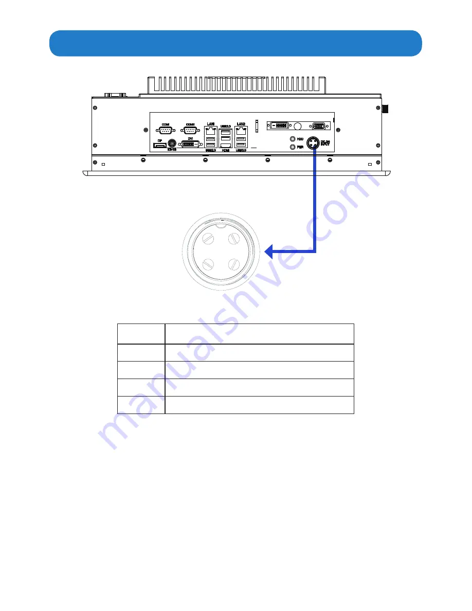
                         Pins in the DC-IN power connector

2

3

4

1

Pin NO.

Definition

1

GND

2

24V

3

GND

4

24V

Summary of Contents for ARP-2215AP-G00

Page 1: ...ARP 2215AP G00 ARP 2217AP G00 ARP 2219AP G00 ARP 2221AP G00 ARP 2200AP G00 Series Industrial Touch Panel Computer USER MANUAL Talk to us We listen ...

Page 2: ... the supplier make sure that it is certified by the local and applicable national standards If the power cable is faulty in any way please contact the manufacturer or the nearest authorized repair service provider for a replacement The power supply cord is used as the main disconnect device Ensure that the socket outlet is easily accessible after installation Overloaded AC outlets extension cords ...

Page 3: ...Mounting the computer 19 Connecting to a display 21 Connecting to keyboard or mouse 22 Connecting to network 23 Connecting the power supply 24 Installing memory module expansion card 26 Adjustment on touch screen 29 Chapter 4 BIOS Setup 31 Introduction 31 Main Menu 33 Advanced Menu 34 H W Monitor Menu 49 Boot Menu 50 Security Menu 51 Exit Menu 52 Chapter 5 Appendix 53 Care and Maintenance 53 Produ...

Page 4: ...ee video connectors DVI HDMI DP Supports up to six serial ports COM1 COM6 Built in expansion connectors MINI PCIE slot the PCIE x 16 slot supports Wi Fi function and Solid State Drives SSD Graphics card Two Dual Gigabit RJ45 LAN ports provides high speed and stable network connections Panel mountable for better stability Strengthened protective glass anti reflective optional Very high bright optio...

Page 5: ...5 Product specifications ...

Page 6: ...fully to make sure there is no damage and all the items are available with your shipment t ures ARP 2200AP G00 Series touch panel computer x1 Unpacking AC power cable x1 DIN Rail AC DC power supply x1 DC power cable x1 Mounting bolts and screws Ordering information ...

Page 7: ...7 Product overview Chapter 2 Basics Side Side Bottom Rear Top Front ARP 2200AP G00 Series Touch Panel Computer ...

Page 8: ...8 ...

Page 9: ...cator The LED lights up when you turn on the system and be off when the system is in standby mode HDD LED Hard Disk Activity LED indicator The read or write activities of the hard disk cause the LED to light up 1 2 3 4 5 6 7 8 9 10 11 12 13 14 1 COM1 port 8 HDD Power indicator 2 COM2 port 9 USB3 0 ports 3 RJ45 LAN Port LAN1 10 HDMI Port 4 USB2 0 ports 11 USB2 0 ports 5 RJ45 LAN Port LAN2 12 DVI co...

Page 10: ...10 COM3 COM6 ports Power button connector CD DVD ROM Drive Slot USB Ports ...

Page 11: ... 2200AP G00 Series touch panel computer Physical dimension 140 0mm 5 51 231 6mm 9 12 111 2mm 4 38 299 8mm 11 80 368 6mm 14 51 276 8mm 10 90 68 9mm 2 71 343 7mm 13 53 261 6mm 10 30 194 3mm 7 65 18 7mm 0 73 353 3mm 13 91 343 7mm 13 53 107 4mm 4 23 For ARP 2215AP G00 24 7mm 0 97 ...

Page 12: ...P 2217AP G00 269 3mm 10 61 194 3mm 7 65 261 6 10 30 386 7mm 15 23 353 3mm 13 91 338 8mm 13 34 403 4mm 15 88 119 9mm 4 72 312 6mm 12 31 377 2mm 14 85 138 1mm 5 44 113 1mm 4 45 89 5mm 3 52 144 9mm 5 71 38 0mm 1 50 ...

Page 13: ... For ARP 2219AP G00 299 7mm 11 80 145 0mm 5 71 120 0mm 4 73 344 9mm 13 58 370 8mm 14 60 58 1mm 2 29 252 4mm 9 94 82 3mm 3 24 426 2mm 16 78 261 6mm 10 30 91 9mm 3 62 452 1mm 17 80 113 1mm 4 46 89 5mm 3 52 ...

Page 14: ...ength W Overall Width H Overall Height Cutout Size ARP 2215AP G00 14 51 368 6mm 11 80 299 8mm 5 51 140 0mm 13 75 x 11 10 inch 349 3 x 281 9 mm ARP 2217AP G00 15 88 403 4mm 13 34 338 8mm 5 71 144 9mm 15 07 x 12 51 inch 382 8 x 317 8 mm ARP 2219AP G00 17 80 452 1mm 14 60 370 8mm 5 71 145 0mm 16 98 x 13 78 inch 431 3 x 350 0 mm ARP 2221AP G00 20 98 533 0mm 12 99 330 0mm 5 78 146 7mm 19 92 x 12 35 inc...

Page 15: ...ctors are located at the bottom of ARP 2200AP G00 Series touch panel computer Chapter 3 Connections This section describes the connections connectors available on the ARP 2200AP G00 Series touch panel computer ...

Page 16: ...ial port COM1 COM2 6 7 8 9 1 2 3 4 5 Pin NO RS 232 mode RS 422 mode RS 485 mode 1 DCD TX RTX 2 RXD RX N A 3 TXD TX RTX 4 DTR RX N A 5 GND GND GND 6 DSR N A N A 7 RTS N A N A 8 CTS N A N A 9 5V 12V RI 5V 12V RI 5V 12V RI ...

Page 17: ...C No connection 9 RXD1 T M D S Data 1 10 RXD1 T M D S Data 1 11 GND T M D S Data 1 Shield 12 NC No connection 13 NC No connection 14 DVIVCC 5V power input 15 GND Ground 16 HPD Hot plug detect 17 RXD0 T M D S Data 0 18 RXD0 T M D S Data 0 19 GND T M D S Data 0 Shield 20 NC No connection 21 NC No connection 22 GND T M D S Clock Shield 23 RXDC T M D S Clock 24 RXDC T M D S Clock 25 NC No connection 2...

Page 18: ...18 Pins in the DC IN power connector 2 3 4 1 Pin NO Definition 1 GND 2 24V 3 GND 4 24V ...

Page 19: ...ies touch panel computer within the place on a board or a wall where the mounting holes are pre drilled Turn to the back of the unit and the wall align the mounting bolts installed on the four sides of ARP 2200AP G00 Series touch panel computer with the mounting holes on the wall or board Step1 There are mounting slots located on the four sides of the ARP 2200AP G00 Series touch panel computer As ...

Page 20: ...n the M4 sized mounting screws into the wall and board through the mounting bolts and mounting holes and make sure the ARP 2200AP G00 Series touch panel computer is correctly and securely seated onto the board or wall ...

Page 21: ...puter Connect the other end of the DVI cable to the DVI port of a display 1 Connecting to a display through DVI port ARP 2200AP G00 HDMI port Display HDMI port HDMI cable not supplied Connect one end of the HDMI to the HDMI port of the ARP 2200AP G00 Series touch panel computer Connect the other end of the HDMI to the HDMI port of a display 2 Connecting to a display through HDMI port ...

Page 22: ...re 1 You can also insert a PS2 type keyboard or a PS2 type mouse not supplied to your computer Figure 2 ARP 2200AP G00 ARP 2200AP G00 DP port Display DP port Display cable not supplied Connect one end of the display cable to the DP port of the ARP 2200AP G00 Series touch panel computer Connect the other end of the display cable to the DP port of a display 3 Connecting to a display through Display ...

Page 23: ...e jack Modem Connecting to network Connect one end of the RJ45 LAN cable to the LAN port of the ARP 2200AP G00 Series touch panel computer Connect the other end of the RJ45 LAN cable to the LAN port of a modem LAN port LAN port RJ45 LAN cable not supplied ARP 2200AP G00 ...

Page 24: ...onnecting the power supply AC outlet Follow the steps below to connect the power supply 8 Important Before you use the power supply please correctly and securely connect the supplied AC power cable to the terminal of L for live wire N for neutral wire and Ground on the power supply and connect the supplied DC power cable to the Power and Ground terminals AC power cable supplied DC power cable supp...

Page 25: ...e of protection the power supply has to be installed in a specific IP rating enclosure Screws Industrial Enclosure Step1 Step2 Step3 In order to correctly install the power supply the specific dimensions for the power supply are indicated in the diagram below DIN rail Power supply Front View Top View Side View 111mm 4 37 75mm 2 95 150W DIN rail power supply ...

Page 26: ...ay be damaged Before you install the memory module or expansion card please follow the instructions below to open the bottom cover of the ARP 2200AP G00 Series touch panel computer 1 As shown in the figure below remove the screws on the sides of the bottom cover 2 Then remove the bottom cover of the ARP 2200AP G00 Series touch panel computer you will find the DDR3 SO DIMM slot MINI_PCIE slot and P...

Page 27: ...es the break on the slot Step 3 Firmly insert the DIMM into the slot until the retaining clips at both ends fully snap back in place and the DIMM is properly seated Note The DIMM only fits in one correct orientation It will cause permanent damage to the motherboard and the DIMM if you force the DIMM into the slot at incorrect orientation ...

Page 28: ...is switched off and the power cord is unplugged Please read the documentation of the expansion card and make necessary hardware settings for the card before you start the installation Step 2 Remove the system unit cover if the motherboard is already installed in a chassis Step 3 Remove the bracket facing the slot that you intend to use Keep the screws for later use Step 4 Align the card connector ...

Page 29: ...ftware follow the several steps as below 1 Double click the setup to start to install the calibration software 2 Click next to continue and go ahead following the dialog window 3 Restart the computer to finish the installing 4 Now the shortcuts of USB Controller can be found on the desktop ...

Page 30: ...open the USB controller window as below 2 Select the Tools of the eGalaxTouch screen and click the 4 Points Calibration then click OK for video calibration 3 Use the point of something such as the pen to calibrate the four points of the display 4 Once calibrated the touchscreen will be ready to use automatically each time the system is restarted ...

Page 31: ...tl Alt Delete or by pressing the reset button on the system chassis You may also restart by turning the system off and then back on Because the UEFI software is constantly being updated the following UEFI setup screens and descriptions are for reference purpose only and they may not exactly match what you see on your screen UEFI Menu Bar The top of the screen has a menu bar with the following sele...

Page 32: ...ions on the menu bar and use key or key to move the cursor up or down to select items then press Enter to get into the sub screen You can also use the mouse to click your required item Please check the following table for the descriptions of each navigation key ...

Page 33: ... etc When you enter the UEFI SETUP UTILITY the Main screen will appear and display the system overview System Date Use this item to specify the system date Manually enter the day month and year System Time Use this item to specify the system time Manually enter the hour minute and second Press Esc to return to the Main Menu screen ...

Page 34: ...ROM This convenient UEFI update tool allows you to update the system UEFI without entering operating systems such as MS DOS or Windows first Just save the new UEFI file to your USB flash drive floppy disk or hard drive and launch this tool then you can update your UEFI in a few clicks without preparing an additional floppy diskette or other complicated flash utility Please note that the USB flash ...

Page 35: ...echnology Please note that enabling this function may reduce CPU voltage and lead to system stability or compatibility issues with some power supplies Please set this item to Disabled if above issues occur Intel Turbo Boost Technology Use this to enable or disable Intel Turbo Boost Mode Technol ogy Turbo Boost Mode allows processor cores to run faster than marked frequency in specific conditions T...

Page 36: ...et In C1 power state the processor maintains the context of the system caches CPU C3 State Support Use this to enable or disable CPU C3 report to OS CPU C6 State Support Use this to enable or disable CPU C6 report to OS Package C State Support Configure options that will be programmed into C State package limit register The default value is Auto CPU Thermal Throttling Use this to enable the CPU in...

Page 37: ...ws you to select PCIE1 Link Speed The default value is Auto Share Memory This allows you to configure share memory The default value is Auto IGPU Multi Moniter This allows you to enable or disable IGPU Multi Moniter The de fault value is Disabled If you wish to install a PCI Express card under Windows XP VistaTM OS please disable this option Render Standby Use this to enable or disable Render Stan...

Page 38: ...ernal graphics device LCD Panel Resolution Select the LCD panel resolution Backlight Control Use this to configure Backlight Control settings Panel Color Depth Select LFP Panel Color Depth Panel Backlight Brightness Adjust Panel Backlight Brightness Level ...

Page 39: ...d HD Audio Front Panel Onboard HDMI HD Audio This allows you to enable or disable the Onboard HDMI HD Au dio Onboard LAN 1 This allows you to enable or disable the Onboard LAN 1 Onboard LAN 2 This allows you to enable or disable the Onboard LAN 2 Restore on AC Power Loss This allows you to set the power state after an unexpected AC power loss If Power Off is selected the AC power remains off when ...

Page 40: ...1 SATA2_2 and SATA2_3 ports Configuration options IDE Mode AHCI Mode and RAID Mode The default value is IDE Mode AHCI Advanced Host Controller Interface supports NCQ and other new features that will improve SATA disk performance but IDE mode does not have these advantages Hard Disk S M A R T Use this to enable or disable S M A R T Self Monitoring Analy sis and Reporting Technology Press Esc to ret...

Page 41: ...nter to view the following screen Intel R Rapid Start Technology Use this to enable or disable Intel R Rapid Start Technology Intel R Rapid Start Technology is a new zero power hibernation mode which allows users to resume in just 5 6 seconds The de fault is Disabled ...

Page 42: ...rt Connect Technology Use this to enable or disable Intel R Smart Connect Technology Intel R Smart Connect Technology keeps your e mail and social networks such as Twitter Facebook etc updated automatically while the computer is in sleep mode The default is Enabled Press Esc to return to the Advanced Menu screen ...

Page 43: ...e this to enable or disable BIOS Hotkey Pressed MEBx Selection Screen Use this to enable or disable MEBx selection screen Hide Un Configure ME Configuration Use this to hide Un Configure ME without password confirmation prompt MEBx Debug Message Output Use this to enable or disable MEBx debug message output Un Configure ME Use this to enable or disable Un Configure ME without password ...

Page 44: ...se this to enable or disable Alert Specification Format Activate Remote Assistance Process Use this to enable or disable trigger CIRA boot USB Configure Use this to enable or disable USB Configure PET Progress Use this to enable or disable PET Events progress to recieve PET events WatchDog Use this to enable or disable WatchDog Timer ...

Page 45: ...wing screen COM1 COM6 Configuration Use these to set parameters of COM1 COM6 LPT1 Port Configuration Use this set parameters of the onboard parallel port WDT Timeout Reset This allows users to enable disable the Watch Dog Timer timeout to reset system The default value is Disabled ...

Page 46: ...able Check Ready Bit ACPI HPET Table Use this to enable or disable the ACPI HPET Table The default value is Enabled Please set this option to Enabled if you plan to use this motherboard to submit Windows VistaTM certification PS 2 Keyboard Power On Use this to enable or disable the PS 2 keyboard to turn on the system from power soft off mode PCI Devices Power On Use this to enable or disable the P...

Page 47: ...r soft off mode RTC Alarm Power On Use this to enable or disable the RTC Real Time Clock to power on the system USB Keyboard Remote Power On Use this to enable or disable the USB Keyboard Remote to power on the system USB Mouse Power On Use this to enable or disable the USB Mouse to power on the system ...

Page 48: ...options Enabled Enables support for legacy USB Auto Enables legacy support if USB devices are connected Disabled USB devices are not allowed to be used under legacy OS and UEFI setup when Disabled is selected If you have USB compatibility issues it is recommended to select Disabled to en ter OS UEFI Setup Only USB devices are allowed to be used only un der UEFI setup and Windows Linux OS Legacy US...

Page 49: ... hardware on your system including the parameters of the CPU temperature motherboard temperature CPU fan speed chassis fan speed and the critical voltage H W Monitor Menu CHA_FAN1 Setting This allows you to set the chassis fan 1 speed The default value is Full On ...

Page 50: ...ion key 65535 0xFFFF means indefinite waiting Bootup Num Lock If this is set to On it will automatically activate the Numeric Lock after boot up PCI ROM Priority Use this to adjust PCI ROM Priority The default value is Legacy ROM Boot From Onboard LAN Use this to enable or disable Boot From Onboard LAN Boot Failure Guard Enable or disable Boot Failure Guard Boot Failure Guard Count Enable or disab...

Page 51: ... is set then this only limits access to setup and is only asked for when entering Setup If ONLY the user s password is set then this is a power on password and must be entered to boot or enter Setup In Setup user will have administrator rights The password length must be in the following range Minimum length 3 Maximum 20 ...

Page 52: ...ou select this option the following message Discard changes and exit setup will pop out Select OK to exit the UEFI SETUP UTILITY without saving any changes Discard Changes When you select this option the following message Discard changes will pop out Select OK to discard all changes Load UEFI Defaults Load UEFI default values for all options The F9 key can be used for this operation Launch EFI She...

Page 53: ... chips Position your system unit away from direct sunlight moisture dust oil and thoroughfare Never expose the unit to harsh jarring Ensure that all ventilation outlets are always free from obstruction To protect components against damage from static electric discharge you should Use a grounding wrist strap The strap will have an alligator clip at the end of a shielded wire lead Clip it to a groun...

Page 54: ...plied by Arista Corporation The Limited Warranty does not cover damages and or failures which result from negligence accidents misuse abuse mishandling misapplication alteration faulty installation set up adjustment improper maintenance power surge problems with electrical stability failure to maintain environmental conditions within operating range specified by the manufacturer relocations or att...

Page 55: ... department in 14 calendar days after the product is received Customer can request either return for credit or replacement If replacement is requested Arista will ship the replacement in 7 calendar days and invoice the customer for the replacement A credit memo will be issued to the customer after the DOA product is received and verified Evaluation Return The customer must notify Arista s RMA depa...

Page 56: ... for the RMA product while in transit to Arista We urge customers to pack the RMA product carefully to avoid transit damage Refused Shipment Restocking Fees If a customer refuses a shipment credit will be issued after the refused product is received and verified by Arista The shipping charge plus 15 restocking fees will be billed to the customer 6 RMA Shipping Instruction Product Non Acceptance Pr...

Page 57: ...rporation be held liable for monetary and or non monetary damages resulting from the normal or abnormal usage of our products Use distribution and or similar engagement of our products constitute implied agreement to these and similar Arista Corporation Limited Liability policies Arista Corporation is not liable for damages or reimbursement for lost time lost revenue cost of having someone remove ...

Page 58: ...rs for their personal archival purposes The manufacturer reserves the right to revise this user s manual and all accompanying documentation and to make changes in the content without obligation to notify any person or organization of the revision or change IN NO EVENT WILL THE VENDOR BE LIABLE FOR DIRECT INDIRECT SPECIAL INCIDENTAL OR CONSEQUENTIAL DAMAGES ARISING OUT OF THE USE OR INABILITY TO US...

Page 59: ...Arista Corporation 40675 Encyclopedia Circle Fremont CA 94538 U S A Tel 510 226 1800 Fax 510 226 1890 http www goarista com Talk to us We listen TM ...

Reviews: