Chapter 4: Cabling the Switch
Connecting Serial and Management Cables
Quick Start Guide: 7000 Series 2 RU Data Center Switches
21
Step 2
Attach the appropriate lugs to the source DC wires.
Step 3
Use DC cables with either insulated crimp-on spade lugs or insulated crimp-on ring
connectors.
Step 4
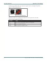
Connect the DC-input wires to the terminal block in this order:
•
Ground wire to the Protective Earth (PE
) terminal.
•
Negative source DC cable to the negative (- / -48V) terminal.
•
Positive (+) source DC cable to the positive (+ / RTN) terminal.
4.2
Connecting Serial and Management Cables
The accessory kit includes the following cables:
•
RJ-45 to DB-9 serial adapter cable.
•
RJ-45 Ethernet cable.
Table 4-1
lists the pin connections of the RJ-45 to DB-9 adapter cable.
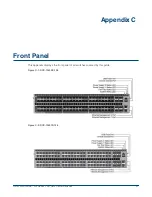
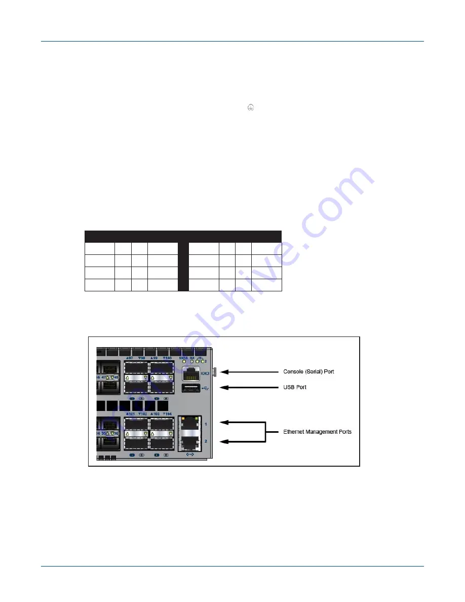
The front panel contains the console, management, and USB ports.
Figure 4-6
displays the ports on
the DCS-7050SX-128 switch.
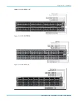
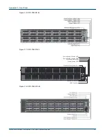
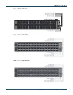
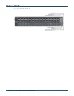
Appendix C
displays the front panel of all switches covered by this guide.
Figure 4-6: Front Panel Ports
Connect the front panel ports as follows:
•
Console (Serial) Port:
Connect to a PC with the RJ-45 to DB-9 serial adapter cable.
The switch uses the following default settings:
•
9600 baud
•
No flow control
•
1 stop bit
Table 4-1 RJ-45 to DB-9 Connections
RJ-45
DB-9
RJ-45
DB-9
RTS
1
8
CTS
GND
5
5
GND
DTR
2
6
DSR
RXD
6
3
TXD
TXD
3
2
RXD
DSR
7
4
DTR
GND
4
5
GND
CTS
8
7
RTS
Summary of Contents for DCS-7050SX-128
Page 38: ...36 Quick Start Guide 7000 Series 2 RU Data Center Switches Appendix C Front Panel ...
Page 40: ...38 Quick Start Guide 7000 Series 2 RU Data Center Switches Appendix D Rear Panel ...
Page 44: ...42 Quick Start Guide 7000 Series 2 RU Data Center Switches Appendix F Taiwan RoHS Information ...


