background image

48

GB

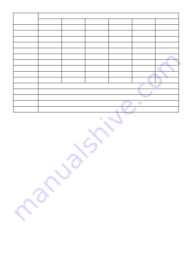
Figure 1 

Model

12P CA-E 

16P CA-E  20P CA-E  12HP CA-E  16HP CA-E  20HP CA-E

ø - mm 

495

495

495

495

495

495

mm 230

230

230

230

230

230

mm 310

310

310

310

310

310

mm 56

56

56

56

56

56

ø - mm

80 

80 

100

 100 

100 

100

mm 

1200 

1450 

1700

 1200

 1450 

1700

mm 

1115 1365 1615 1115 1365 1615

mm 

175 min

175 min

175 min

175 min

175 min

175 min

M

 mm  520 min.

520 min.

520 min.

520 min.

520 min.

520 min.

mm  250 min.

250 min.

250 min.

250 min.

250 min.

250 min.

b1 

Water inlet

b2 

Water outlet

Drain / recirculation

Gas supply

Flue gas exhaust

Carry out the installation as to standards.

STANDARDS FOR INSTALLATION

Place the wall mounted heater near an out-

side wall or a chimney (

fi

 gure 8) on which 

the 

fl

 ue gas exhaust / outside air intake de-

vice can be installed.

When selecting the position of the terminal 

on an outside wall, follow the applicable lo-

cal and national regulations.

If the water heater is to be installed in a 

corner between two walls, leave, between 

the wall and the heater, enough space for 

installation and removal of the components.

POSITIONING

Summary of Contents for 12HP CA-E

Page 1: ...S AD ACCUMULO 4 2G776ͻ62G 82L 244G G 2F A 82Eͻ7 D65 EFAD286 I2F6D 62F6D F EFDGL A B6D EF2 2L A 6 6 2 2 GF6 L A 6 7D EFDG4F A E BAGD EF2 2F A 6F 6 FD6F 6 83 EF2 2F A 2 5 2 F6 2 46 EFDG4F A E ELECTRONIC 12 16 20 HP CA E ...

Page 2: ...valvola di sicurezza un dispositivo di interruzione di carico idraulico I suddetti accessori sono necessari ai fini dell esercizio in sicurezza degli scaldacqua mede simi La pressione di esercizio massima deve essere di 0 7 MPa 7 bar Durante la fase di riscaldamento dell acqua il gocciolamento del dispositivo è normale in quanto dovuto all espansione del volume di acqua all interno del prodotto Pe...

Page 3: ...redispuestos Only for equipped appliances Nur für die dafür vorgesehenen Geräte bestimmt Enkel voor voorbestemde toestellen Sómente para aparelhos pre vistos Tylko w wybranych urządzeniach Pouze pro spotrebice k tomu urcené Iba pre spotrebice k tomu urcené Csak előre beállított készülékekre Doar pentru echipamente avand anumite componente ТОЛЬКО ДЛЯ ОПРЕДЕЛЕННЫХ МОДЕЛЕЙ A B ...

Page 4: ... di apparecchiature elettriche ed elettroniche RAEE Il simbolo del cassonetto barrato riportato sull apparecchiatura o sulla sua confezione indi ca che il prodotto alla fine della propria vita utile deve essere raccolto separatamente dagli altri rifiuti L utente dovrà pertanto conferire l apparecchiatura giunta a fine vita agli idonei centri co munali di raccolta differenziata dei rifiuti elettrote...

Page 5: ...ale ed europea assolve a diverse funzioni di servizio di strema utilità per l utente Una valvola gas a funzionamento elettrico che interrompe l afflusso del gas secondo le procedure di controllo della scheda elettronica punto precedente Un bruciatore circolare in acciaio inox adatto a tutti i tipi di gas naturale metano e liqui do studiato per garantire un alta efficienza ed una silenziosità di funzio...

Page 6: ...a acqua c scarico ricircolazione d alimentazione gas e scarico fumi Eseguire l installazione in conformità alle norme UNI CIG 7129 7131 NORMATIVE APPLICABILI PER L INSTALLAZIONE Posizionare l apparecchio a muro a ridosso di una parete esterna o di una canna fuma ria figura 8 su cui sia possibile installare il dispositivo di scarico fumi presa d aria di combustione Per la scelta della posizione del...

Page 7: ...combustione Se il tubo di scarico attraversa locali freddi non riscaldati è bene prevede re una isolazione termica onde evitare la formazione di condense In nessun caso la cappa fumi deve es sere eliminata modificata o sostituita in quanto parte integrale di tutto il si stema combustione dello scaldacqua a gas La corretta installazione del tubo di scarico fumi è esclusiva responsabilità dell insta...

Page 8: ... garanzia che accompagna lo scaldacqua Nella fase di riscaldamento la val vola idraulica deve necessariamente gocciolare Questo gocciolamento é normale e deve cessare quando l ap parecchio ha raggiunto la temperatu ra impostata Bisogna prevedere un imbuto collegato allo scarico come illustrato di seguito figura 3 Assicurarsi facendo scorrere l acqua per un certo periodo di tempo che non vi siano n...

Page 9: ...di scarico precedentemente collegato al raccordo R N B Lo svuotamento completo si realizza per sifonaggio Ciò si ottiene collegando un tubo flessibile al raccordo di scarico come riportato in figura 4 ALLACCIAMENTO ALLA RICIRCOLAZIONE RICIRCOLAZIONE Qualora l impianto di utenza comprenda anche il circuito per la ricircolazione dell acqua sani taria si può usare lo stesso raccordo R usato per lo sc...

Page 10: ... rete elettrica devono es sere eseguiti con allacciamento fisso non con spina mobile e dotati di un interruttore bipolare con distanza di apertura dei contatti di almeno 3 mm Lo scaldacqua funziona con corrente alter nata come indicato nella tabella dei Dati Tec nici rif paragrafo 3 nella quale viene indica to anche l assorbimento massimo Sostituzione del cavo elettrico di alimenta zione In caso d...

Page 11: ...ccolo e collegare il connettore femmina del protettore fumi al corrispondente maschio presente all interno del cablaggio figura 7 5 Inserire il connettore di giunzione dei cavi nel foro di passaggio e rimontare il tappo pressa cavo sullo zoccolo figura 7 6 Il dispositivo non deve essere rimosso per nessun motivo in caso di cattivo funzio namento della canna fumaria i prodotti della combustione e q...

Page 12: ...i 3 d 2 5 m max Per maggiori elementi in ordine all installazione consultare la norma UNICIG 7129 e UNICIG 7131 SCHEMA COLLEGAMENTO APPARECCHIO 8 Se l apparecchio dovesse andare in blocco si dovrà operare come segue Verificare se il collegamento elettrico non è interrotto o se i terminali di connessione non siano ossidati Attendere 10 minuti dopo che si è verificato il blocco per consentire il raff...

Page 13: ...e avere un apertura pari a 6 cm2 per ogni kW installato e comunque mai inferiore a 100 cm2 praticata diretta mente sul muro verso l esterno l apertura deve essere il più vicino possi bile all altezza del pavimento deve esse ISTRUZIONI TECNICHE PER L INSTALLAZIONE re non ostruibile e protetta da una griglia che non riduca la sezione utile di passag gio dell aria IMPORTANTE Un aerazione corretta può...

Page 14: ...te L apertura non è sufficiente ad alimentare l apparecchio e il ventilatore per adeguare I apertura vedi tabella a fondo pagina Portata massima in m3 h Velocità entrata aria in m s Sezione netta aggiuntiva passaggio aria in cm2 fino a 50 1 140 oltre 50 fino a 100 1 280 oltre 100 fino a 150 1 420 La sezione dell apertura deve essere di mi sura adeguata L apertura è sufficientemente ampia da con sentir...

Page 15: ...ocale all altro è assicurato fig 13 DISPOSITIVO CONTROLLO EVACUAZIONE FUMI Questo tipo di apparecchi B11BS sono forni ti di un dispositivo che in caso di immissione nell ambiente dei prodotti nocivi della com bustione interrompe automaticamente l arri vo del gas al bruciatore principale Il disposi tivo si riattiva automaticamente ad ogni ciclo di riscaldamento L aerazione del locale attiguo non è ...

Page 16: ...mente alla rete idraulica di alimentazione di utilizzazio ne e di scarico verificando il rispetto dei DATI TECNICI il serbatoio sia riempito completamente d acqua sia stato effettuato il collegamento alla rete di alimentazione elettrica di 230V lo scaldacqua sia collegato al sistema di evacuazioni fumi come previsto sia stato eseguito correttamente il collegamento del PROTETTORE FUMI come illustrat...

Page 17: ...sicurezza Sono funzioni sempre attive quando l apparecchio è collegato alla rete elettrica e che riguar dano tutti quei controlli che hanno lo scopo di fornire all apparecchio protezioni di sicurezza attiva e sono Sovra temperatura Se per cause anomale la temperatura dell acqua con tenuta nello scaldacqua superasse i 99 C interviene un termostato di sicurezza che inter rompendo il circuito elettri...

Page 18: ...o se non for nito con l apparecchio dovrà essere ri chiesto come accessorio originale al produttore e non può per nessun motivo avere origini diverse L operazione si può fare senza smontare il gruppo gas ma semplicemente figura 16 svitare le quattro viti di fissaggio della pan nello supporto comandi svitare l ugello del bruciatore 9 sostituire l ugello con quello relativo al gas diverso da quello ...

Page 19: ...ata specificatamente sulla valvola a mezzo di un manometro deve avere dei valori come quelli riportati nella tabella B Pressione di alimentazione del gas Pressione al bruciatore Unità di misura mbar 12P CA E 16P CA E 20P CA E 12HP CA E 16HP CA E 20HP CA E GAS metano G20 20 18 6 18 1 18 5 18 8 18 6 18 6 GAS liquido G30 Butano 29 27 5 27 5 27 4 27 4 27 8 27 8 GAS liquido G31 Propano 37 35 2 35 5 35 ...

Page 20: ... dell apparecchio DEMOLIZIONE E SMALTIMENTO L apparecchio non contiene sostanze o com ponenti pericolosi per la salute dell uomo o per l ambiente essendo realizzato con m teriali completamente riciclabili o smaltibili normalmente 18 19 SCHEMA ELETTRICO Vedi figura 20 Legenda A Morsettiera allacciamento alla rete B Interruttore generale C Termostato regolazione temperatura D Pulsante di Reset E Spi...

Page 21: ...roporzionale alla temperatura media alla composi zione chimica dell acqua e alla quantità dei prelievi L anodo montato in fabbrica è previsto per una efficienza di circa cinque anni nelle condizioni di esercizio medie È comunque preferibile procedere ogni 18 24 mesi alla verifica dell anodo te nendo conto che esso deve presentare una superficie abbastanza omogenea Quando il diametro scende al di sot...

Page 22: ...apparecchio dalla rete di alimentazione e svuotarlo utilizzando il rubinetto di scarico fig 2 riempire l accumulo con una soluzione di acqua ed acido in maniera conforme alle istruzioni d impiego dello stesso Iasciare agire la soluzione ed effettuare possibilmente con una pompa un ricir colo di acqua tra tubo uscita acqua cal da e rubinetto di scarico svuotare l accumulo ed effettuare un lavaggio pr...

Page 23: ...re calorifico superiore mg kWh 129 143 125 Consumo annuo di energia elettrica AEC kWh annum 9 14 37 Consumo annuo di combustibile AFC GJ annum 14 14 24 Acqua mista a 40 CV40 l 156 182 221 Temperatura di Set point out of the box C 60 60 60 Setting di riferimento del termostato E Eco E Eco E Eco Pressione di allacciamento gas Metano G20 mbar 20 20 20 Gas liquido butano G30 mbar 28 30 28 30 28 30 Gas...

Page 24: ...stante tra i 25 C e i 50 C il batterio della Legionella potrebbe crescere all interno del serbatoio In questi casi per ridurre la proliferazione della Legionella è necessario ricorrere al cosiddetto ciclo di sanificazione termica Lo scaldacqua ad accumulo di tipo elettromeccanico viene venduto con un termostato impostato ad una tem peratura superiore a 60 C ciò significa che consente l effettuazion...

Page 25: ...ctuées par le personnel spécialisé CE PRODUIT EST CONFORME À LA DIRECTIVE EU 2012 19 EU Le symbole de la poubelle barrée d une croix appliqué sur l appareil indique que le produit en fin de vie ne doit pas être jeté avec les déchets ménagers mais déposé dans un point de collecte approprié pour appareils électriques et électroniques ou être remis au commerçant lors de l achat d un nouvel appa reil ...

Page 26: ...glable sur plusieurs positions un système de sécu rité à thermocouple un limiteur de température qui interrompt l alimentation de gaz en cas de fonctionnement anormal un brûleur circulaire silencieux en acier inox adaptable à tous les types de gaz un groupe de sécurité homologué comprenant une soupape tarée à 7 bars un clapet anti retour un dispositif rationnel de vidange un allumage piézo électri...

Page 27: ...rculation d alimentation gaz e Echappement fumées N B Le raccordement doit être réalisé conformément aux normes et réglementations en vigueur NORMES APPLICABLES POUR L INSTALLATION Positionner l appareil à installer au mur contre une paroi extérieure ou un conduit de fumées figure 8 où pouvoir installer le dispositif d évacuation des fumées la prise d air de combustion Pour le choix de la position...

Page 28: ...lité de l installateur Ne jamais enlever ce dispositif en cas de mauvais fonctionnement du con duit de fumée les produits de la combustion et donc également l oxyde de carbone peuvent refouler dans les lieux en provoquant un grave dan ger pour les occupants Pour ce même motif en cas de mauvais fonctionnement le remplacement de ce dispositif doit être effectué avec des pièces de rechange d origine e...

Page 29: ...accompagnant le chauffe eau Pendant la phase de chauffage la soupape hydraulique doit forcément goutter Ce suintement est normal et doit cesser quand l appareil a at teint la température programmée Il faut prévoir un entonnoir branché à la vidange comme cela est illustré ci dessous figure 3 Il faut s assurer en faisant couler l e au pendant un certain temps que des corps étrangers ne risquent pas d ...

Page 30: ...l du chauffe eau ouvrir le robinet de vidange branché auparavant au raccordement R RACCORDEMENT À LA RECIRCULATION RECIRCULATION Si l installation prévoit également le circuit de recirculation de l eau sanitaire on peut utiliser le même raccord R utilisé pour la vidange Le schema 4 montre le raccordement qu il faut effectuer dans ce cas utilisation recirculation vidange soupape de sécurité alimentat...

Page 31: ... branchements au réseau électrique doi vent être assurés par un branchement fixe sans fiche amovible et munis d un interrup teur bipolaire avec une distance d ouverture des contacts d au moins 3 mm Le chauffe eau fonctionne avec du courant alternatif comme cela est indiqué sur le tableau des Données Techniques cf paragraphe 3 où est indiquée également l absorption maxi male Substitution du câble él...

Page 32: ... le bouchon serre câble monté sur le socle et raccorder le connecteur femelle du dispositif de protection des fumées avec le connecteur mâle correspondant qui se trouve à l intérieur du câblage figure 7 5 Il ne faut enlever le dispositif pour aucune raison en cas de mauvais fonctionnement du conduit de fumées les produits de combustion l oxyde de carbone aussi par conséquent risquent de se déverse...

Page 33: ...nient et de l éliminer N B Le raccordement doit être réalisé conformément aux normes et réglementations en vigueur SCHÉMA DE RACCORDEMENT DE L APPAREIL SCARICO DIRETTO ALL ESTERNO SCARICO DIRETTO IN CAMINO O IN UNA CANNA FUMARIA COLLETTIVA RAMIFICATA Per maggiori elementi riguardanti l installazione consultare le norme UNICIG 7129 e UNICIG 7131 Per maggiori elementi riguardanti l installazione con...

Page 34: ...iateur alors que dans le cas 3 la grille est bouchée parce qu elle n a pas de protection figure 10 l ouverture est suffisamment am ple pour permettre l aération adéquate de l appareil figure 11 l ouverture n est pas suffisante pour alimenter l appareil et la cheminée qui doit avoir sa propre ouverture de prise d air s adresser au fabricant de la cheminée figure 12 l ouverture est suffisamment am ple pou...

Page 35: ...sible de faire l ouverture près du sol il faut augmenter la section de l ouverture d au moins 50 S il y a d autres éléments dans la pièce qui ont besoin d air pour leur fonctionne ment la taille de la section pour l ouver ture permettant l aération doit être cal culée de façon adéquate par ex pour les électroventilateurs cf figure 14 La hotte d aspiration d une cuisine par exemple doit être consid...

Page 36: ...mmeuble et n est pas un local présentant des risques d incendie par exemple un dépôt de combustibles un garage etc d la pièce contiguë a une aération directe correcte et le passage de l air d une pièce à l autre peut être assuré DISPOSITIF DE COMMANDE FUMÉE Ce type d appareil B11BS sont munis d un dispositif qui en cas d entrée dans l environ nement de produits nocifs de la combustion arrête autom...

Page 37: ...S TECHNIQUES du paragraphe 3 sont bien re spectées si le réservoir est tout à fait plein d eau si le branchement au réseau d alimentation électrique de 230V a été effectué si le chauffe eau est raccordé au système d évacuation des fumées comme cela est prévu dans les paragraphes si le branchement avec le dispositif de PROTECTION DES FUMÉES a été exécuté de façon correcte comme l illustre le paragrap...

Page 38: ...ières de sûreté branché au courant et qui concernent tous les contrôles qui ont pour but de fournir à l appa reil des protections de sûreté actives il s agit de Excès de température Si la température de l eau contenue dans le chauffe eau dépas se 99 C un thermostat de sûreté intervient pour bloquer l appareil en coupant le circuit électrique de la soupape du gaz et signale la situation en allumant ...

Page 39: ... allumage SUBSTITUTION DU GICLEUR Pour adapter le chauffe eau à un gaz différent de celui du réglage il faut rempla cer le gicleur du brûleur ATTENTION le nouveau gicleur s il n est pas fourni avec l appareil doit être de mandé au fabricant comme accessoire d origine et ne peut en aucun cas avoir une autre origine L opération peut se faire sans démonter l u nité du gaz mais simplement figure 16 en d...

Page 40: ...entation relevée au niveau de la prise de pression à l entrée et in diquée de façon spécifique sur la soupape au moyen d un manomètre doit avoir des valeurs comme celles qui sont reportées dans le tableau B Pression d alimentation du gaz Pression au niveau du brûleur Unité de mesure mbar 12P CA E 16P CA E 20P CA E 12HP CA E 16HP CA E 20HP CA E GAZ méthane G20 20 18 6 18 1 18 5 18 8 18 6 18 6 GAZ g...

Page 41: ...ÉLIMINATION L appareil ne contient pas de substances ou de composants dangereux pour la santé de l homme ou pour l environnement car il a été réalisé avec des matériels complètement recyclables ou s éliminant normalement 18 19 SCHÉMA ÉLECTRIQUE Cf figure 20 Légende A Bornier de branchement du courant B Interrupteur général C Thermostat réglage température D Bouton de réarmement E Voyant de blocage...

Page 42: ... proportionnelle à la température moyenne à la composition chimique de l eau et à la quantité de sou tirages Procéder au contrôle de l anode environ chaque 18 24 mois en tenant compte qu elle doit présenter une surfa ce assez homogène Si son diamètre se réduit au dessous de 10 12 mm remplacer par une nouvelle anode originale N B L anode est montée sous le capu chon blanc situé sur la partie supéri...

Page 43: ... d eau entre le tuyau de sortie de l eau chaude et le robinet de vidange vider l accumulateur et effectuer un la vage prolongé de passivation en faisant circuler de l eau de réseau Attention à la qualité de l eau Afin de garantir la durée maximum à votre ap pareil il faut respecter certaines règles EAU CALCAIRE prévoir un dispositif effica ce contre le calcaire à base de cristaux de polyphosphates EA...

Page 44: ...ation annuelle d énergie électrique AEC kWh annum 9 14 37 Consommation annuelle de combustible AFC GJ annum 14 14 24 Eau mitigée à 40 C V40 l 156 182 221 Température de consigne au déballage C 60 60 60 Réglage de référence du thermostat E Eco E Eco E Eco Pression de raccordement du gaz Gaz naturel G20 G25 mbar 20 20 20 Gaz liquide butane G30 mbar 28 30 28 30 28 30 Gaz liquide propane G31 mbar 37 3...

Page 45: ... temps des mois ou 2 la température de l eau reste constante entre 25 C et 50 C les bactéries légionelles pourraient se développer à l intérieur du réservoir Dans ces cas pour réduire la prolifération des légionelles il est nécessaire d avoir recours au cycle d assainissement thermique Le chauffe eau à accumulation de type électromécanique est vendu avec un thermostat configuré sur une température ...

Page 46: ...EU 2012 19 EU The barred dustbin symbol appearing on the device indicates that the product must be disposed of separately from household waste once it reaches the end of its lifespan and transferred to a waste disposal site for electric and elec tronic equipment or returned to the dealer when purchasing a new device of the same kind The user is responsible for delivering the decommissioned device ...

Page 47: ... protect against the return of combustion products a gas valve complete with an adjustable termostat with a number of positions a safety system using a thermocouple a temperature limiter that stops the gas supply if operation is not correct a circular low noise stainless steel burner adaptable for use with all types of gas piezoelectric ignition a safety device to protect against the return of flu...

Page 48: ...n 250 min 250 min 250 min b1 Water inlet b2 Water outlet c Drain recirculation d Gas supply e Flue gas exhaust Carry out the installation as to standards STANDARDS FOR INSTALLATION Place the wall mounted heater near an out side wall or a chimney figure 8 on which the flue gas exhaust outside air intake de vice can be installed When selecting the position of the terminal on an outside wall follow t...

Page 49: ...n no case must the fumes hood be eli minated amended or replaced as it is integral part of the entire combustion system of the gas water heater The correct installation of the fumes discharge pipe is the exclusive respon sibility of the installer The device must not be removed for any reason in case of malfunctioning of the flue the combustion products and therefore the carbon monoxide also may fl...

Page 50: ...ter heater During heating the pressure relief valve will necessarily drip This is nor mal and must stop when the heater reaches the set temperature Provide a funnel connected to the drainage system as shown below figure 3 Make sure by letting the water run for some time that there is no swarf sand pipe dope etc in the water sup ply line If any of these enter the pres sure relief or non return valv...

Page 51: ...ting a flexible hose to the drain fitting as shown in figure 4 RECIRCULATION CONNECTION RECIRCULATION Recirculation if the user system includes a circuit for recirculation of the sanitary hot water the same connection R used for drainage can be adopted The circuit beside shows the con nection scheme to be followed in this case figure 5 user Recirculation Drain Safety valve Supply one way valve ...

Page 52: ...pe H03 VV F 3x1 The connection to the electric sup ply must be made using a permanent cable not a plug and have a two pole switch with contact opening distance of at least 3 mm The water heater operates with alternating current as shown in the Technical Data Table ref paragraph 3 which Table also shows the maximum electric rating Replacing the electric supply cable If you replace the electric supp...

Page 53: ...ve the plug fastener fitted to the heater base and connect the female plug of the flue gas protector to the corresponding male plug in the wiring figure 7 5 Insert the cable connector in the cable way hole and refit the plug fastener to the heater base figure 7 6 This device must not be removed for any reason at all In the case of chimney mal function the products of combustion and hence also Carb...

Page 54: ...T DIAGRAM TYPE B SCARICO DIRETTO ALL ESTERNO SCARICO DIRETTO IN CAMINO O IN UNA CANNA FUMARIA COLLETTIVA RAMIFICATA Per maggiori elementi riguardanti l installazione consultare le norme UNICIG 7129 e UNICIG 7131 Per maggiori elementi riguardanti l installazione consultare le norme UNICIG 7129 e UNICIG 7131 d 2d Pente mini 3 d 2 5 m max Ouverture dҋaspiration d min 1 5 m min 2d d 1 m max 2d Pente m...

Page 55: ...ter and the fireplace which must have its own air intake call the fireplace manufacturer figure 12 the opening is large enough to allow adequate aeration of the heater figure 13 the opening is not sufficient to supply air to the heater and to the fireplace which must have its own air intake call the fireplace ma nufacturer figure 14 the opening is not suf ficient to supply both the heater and the fa...

Page 56: ...re other de vices that need air for their operation the section of the aeration opening must be adequately sized as in the case of elec tric extractor fans see figure 14 A suction hood for example for a cooker must be considered to all effects as an electric extractor fan An open fireplace must have its own air intake otherwise a type B gas device cannot be installed in the same room ...

Page 57: ...d FLUES EVACUATION CONTROL DEVICE This type of appliances B11 BS are equipped with a device that in case of flow of toxic fuel products into the environment automatically interrupts the arrival of gas to the main bur ner The device automatically activates again upon every heating cycle The ventilation of the near by premises is no longer sufficient to guarantee suitable venti lation to the premises ...

Page 58: ...nk is completely full The heater is connected to the electric supply at 230V The water heater is connected to a flue gas exhaust system as foreseen in paragraphs 4 5 and 5 The FLUEGAS PROTECTOR has been correctly connected as illustrated in paragraph 5 The room aeration has been checked where the heater is installed also for compliance with the applicable national and local regulations MAX E III I...

Page 59: ...ith active safety protection and that is Over temperature If for any reason the water temperature in the heater exceeds 99 C a safety thermostat interrupts the electric circuit of the gas valve locking the heater out of ser vice The situation is signalled by the red lamp marked RESET Before re starting the water heater acting as shown in item 8 1 you MUST first remove the cause of the critical sit...

Page 60: ... type of gas differing from the pre set one you must re place the burner nozzle WARNING the new nozzle if not supplied with the heater must be ordered from the manufacturer as an original accessory and must not for any reason have any other origin The operation can be carried out without di smantling the gas control unit but simply by figure 16 unscrewing the four fastening screws of the control pa...

Page 61: ...out The gas supply pressure measured at the inlet pressure take off using a pressure gauge and specifically indicated on the valve must have a value as shown in Table B Gas supply pressure Pressure at the burner mbar 12P CA E 16P CA E 20P CA E 12HP CA E 16HP CA E 20HP CA E GAZ méthane G20 20 18 6 18 1 18 5 18 8 18 6 18 6 GAZ G30 Butane 29 27 5 27 5 27 4 27 4 27 8 27 8 GAZ G31 Propane 37 35 2 35 5 3...

Page 62: ...the heater is installed DEMOLITION AND DISPOSAL The water heater does not contain any sub stances dangerous to human health or to the environment as it is entirely manufactu red using materials that can be completely recycled or normally disposed of 18 19 WIRING DIAGRAM See figure 20 Legend A Terminals for electricity supply connection B Main switch C Temperature control thermostat D Reset button ...

Page 63: ...ory is envisioned for an efficiency of ap prox five years in average working con ditions It is however preferable to check the anode every 18 24 months bearing in mind that it must have a sufficiently even surface When the diameter falls below 10 12 mm we recommend replacing it with an original anode NB The anode is mounted underneath the white boss located in the upper part of the appliance 3 For cor...

Page 64: ... to act and possibly with a pump recirculate the water through the hot water outlet pipe and drain cock drain the storage and carry out a prolonged passivation washing by making the mains water circulate Attention to the water quality To assure maximum duration of your applian ce respect certain rules LIMESTONE WATER envision an efficient anti limescale device with polyphosphate crystals base SOFT W...

Page 65: ...ons of nitrogen oxides mg kWh 129 143 125 Annual electricity consumption AEC kWh annum 9 14 37 Annual fuel consumption AFC GJ annum 14 14 24 Mixed water at 40 C V40 l 156 182 221 Set point temperature out of the box C 60 60 60 Thermostat temperature settings E Eco E Eco E Eco Gas supply pressure G20 Methane mbar 20 20 20 G30 Butane LPG mbar 28 30 28 30 28 30 G31 Propane LPG mbar 37 37 37 gas consu...

Page 66: ... the water temperature is constantly maintained between 25 C and 50 C the Legionella bacteria could growth inside the tank In these cases to restrict the Legionella growth it is necessary to perform the so called thermal disinfection cycle This electro mechanical storage water heater is sold with a thermostat set at a temperature higher than 60 C it means it is enabled to carry out a thermal disin...

Page 67: ...67 ...

Page 68: ...420010660100 06 2015 Ariston Thermo SpA Viale Aristide Merloni 45 60044 Fabriano AN Italy Telefono 0732 6011 Fax 0732 602331 info it aristonthermo com www aristonthermo com ...

Reviews: