background image

10 / IT


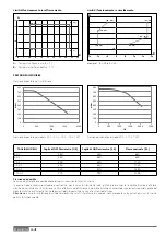
A -

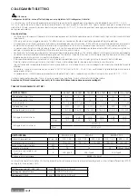
  Temperatura acqua in uscita (°C)

B -

   Temperatura esterna dell’aria  (°C)

Limiti di funzionamento in raffrescamento 

Limiti di funzionamento in riscaldamento

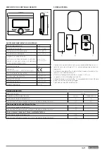
PRESSIONE DISPONIBILE

Pressione disponibile per l’installazione

Pressione disponibile

Le curve indicate tengono conto delle perdite di carico attribuibili all’unità interna.
In questo modo è necessario calcolare e confrontare, con la curva di riferimento (vedi grafi ci), esclusivamente le perdite di carico dell’intero 
circuito per verifi care che l’installazione sia stata effettuata correttamente. E’ possibile installare un circolatore supplementare qualora quello del 
modulo risultasse insuffi ciente. Per i collegamenti elettrici consultare il paragrafo «Circuito elettrico». 

Attenzione: 

in caso di installazione di valvole termostatiche su tutti i terminali o di valvole di zona, prevedere un by pass che assicuri la minima 

portata di funzionamento.

(43 ; 22)

(43 ; 5)

(10 ; 5)

(10 ; 22)

0

5

10

15

20

25

0

5

10

15

20

25

30

35

40

45

50

A

B

(-20 ; 45)

(-10 ; 60)

(35 ; 60)

(35 ; 33)

(15 ; 20)

(-20 ; 20)

0

10

20

30

40

50

60

70

-30

-20

-10

0

10

20

30

40

B

A

100 

200 

300 

400 

500 

600 

700 

800 

0 500 

1000 

1500 

2000 

mbar 

l\h 

100 

200 

300 

400 

500 

600 

700 

800 

0  500  1000 1500 2000 2500 

mbar 

l\h 

TAGLIA MODELLI

Soglia di OFF fl ussimetro [l/h]

Soglia di ON fl ussimetro [l/h]

Flusso nominale [l/h]

40 S

280

360

640

50 S

350

450

800

70 S

490

630

1120

70 S-T

490

630

1120

90 S-T

630

810

1440

110 S-T

770

990

1755

Pressione disponibile per modelli: 40 S - 50 S - 70 S - 70 S-T EXT

Pressione disponibile per modelli: 90 - 110 S-T EXT

1

esempio 1: B = 35 e  A = 33

Summary of Contents for 3300919

Page 1: ...IT NIMBUS PLUS S ISTRUZIONI TECNICHE PER L INSTALLAZIONE E LA MANUTENZIONE TECHNICAL INSTRUCTIONS FOR INSTALLATION AND MAINTENANCE OK ...

Page 2: ...rescamento 14 Collegamenti idraulici e refrigerante Connessione gas refrigerante tra unitá Interna ed esterna 15 Fare il vuoto e verificare la tenuta 15 Carica del gas refrigerante 15 Recupero del refrigerante 16 Connessioni idrauliche unità interna 16 Installazione finale dell intero sistema 17 Collegamenti elettrici Circuito elettrico 18 Tabelle collegamenti elettrci 18 Connessioni elettriche dell...

Page 3: ...nuale Installare l apparecchio su base solida non soggetta a vibrazioni Rumorosità durante il funzionamento Non danneggiare nel forare la parete cavi elettrici o tubazioni preesistenti Folgorazione per contatto con conduttori sotto tensione Danneggiamento impianti preesistenti Allagamenti per perdita acqua dalle tubazioni danneggiate Eseguire i collegamenti elettrici con con duttori di sezione ade...

Page 4: ...amento dell apparecchio o di oggetti circostanti per urti colpi incisioni schiaccia mento Indossare durante le lavorazioni gli indumen ti e gli equipaggiamenti protettivi individuali É vietato toccare il prodotto installato senza calzature o con parti del corpo bagnate Lesioni personali per folgorazione proiezione di schegge o frammenti inalazioni polveri urti tagli punture abrasioni rumore vibraz...

Page 5: ...i oggetti infiammabili Non utilizzare l unità esterna per il trattamento di acque provenienti da processi industriali piscine o acqua sanitaria In tutti questi casi prevedere per l utilizzo dell unità esterna uno scambiatore di calore in posizione inter media L apparecchio non è destinato a essere utilizzato da persone bambini compresi le cui capacità fisiche sensoriali o mentali siano ridotte oppur...

Page 6: ...procedere al successivo riempimento dell intero impianto con acqua trattata Verificare che la pressione massima a livello di fornitura dell ac qua non superi i 5 bar In caso contrario provvedere all installa zione di un riduttore di pressione Per evitare congelamenti nelle tubazioni qualora si rilevino condizioni di rischio il sistema provvede cicli antigelo automa tici Nel caso di mancanza di alim...

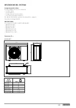
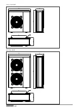
Page 7: ... informazioni sugli accessori disponibili si prega di consultare il Catalogo Prodotti UNITÀ ESTERNA L unità esterna fornita è uno dei modelli seguenti NIMBUS 40 S EXT NIMBUS 50 S EXT NIMBUS 70 S EXT NIMBUS 70 S T EXT NIMBUS 90 S T EXT NIMBUS 110 S T EXT UNITÀ ESTERNA peso 40 S EXT 52 50 S EXT 52 70 S EXT 82 70 S T EXT 90 90 S T EXT 110 110 S T EXT 110 Dimensioni e Pesi 40 50 S EXT 756 383 1016 670...

Page 8: ...8 IT 1106 383 1016 670 ø 10 374 1506 383 1016 670 ø 10 374 70 S 70 S T EXT 9 0 110 S T EXT ...

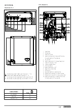
Page 9: ...o 13 Resistenza elettrica supplementare 14 Termostato di sicurezza a riarmo manuale 15 Termostato di sicurezza a riarmo automatico 16 Sonda di temperatura mandata all impianto di riscaldamento raffrescamento UNITÀ INTERNA Dimensioni e Pesi Vista complessiva A Mandata acqua calda fredda verso l impianto G 1 M B Ritorno acqua fredda calda dall impianto G 1 M C Connessione Gas Refrigerante dall unità...

Page 10: ...amenti elettrici consultare il paragrafo Circuito elettrico Attenzione in caso di installazione di valvole termostatiche su tutti i terminali o di valvole di zona prevedere un by pass che assicuri la minima portata di funzionamento 43 22 43 5 10 5 10 22 0 5 10 15 20 25 0 5 10 15 20 25 30 35 40 45 50 A B 20 45 10 60 35 60 35 33 15 20 20 20 0 10 20 30 40 50 60 70 30 20 10 0 10 20 30 40 B A 0 100 200...

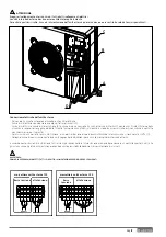
Page 11: ...o l esposizione diretta ai raggi solari Rimuovere il coperchio fig A ed installare la sonda utilizzando il tas sello e la vite in dotazione fig B Effettuare il collegamento tramite un cavo da 2x0 5 mm2 Lunghezza massima di collegamento 50 m Collegare il cavo al morsetto fig C inserendolo dalla parte inferiore dopo aver forato l apposito passaggio Riposizionare il coperchio della sonda A B C SCHEDA PR...

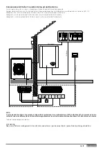
Page 12: ...ntazione corrisponda alla potenza elettrica assorbita dall unità esterna come indicato sulla targa dati dell unità esterna EN 61000 3 12 Verificare la presenza di differenziali e interruttori di sicurezza cor rettamente dimensionati collegati all unità esterna NOTA Le caratteristiche e i codici dell unità esterna sono indicati nella targa dati Distanze minime per l installazione GUIDA ALL INSTALLAZ...

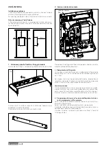
Page 13: ...pertura dei passaggi per i collegamenti Per consentire il passaggio dei cavi rimuovere con l aiuto di un caccia vite le parti pretagliate A del telaio dell unità esterna Per rimuovere efficacemente il materiale mantenere installato il pan nello frontale dell unità Prima del passaggio dei cavi posizionare i passacavi B neri forniti all interno della busta documenti A B A I fori pretagliati per il pa...

Page 14: ...ianto di riscaldamento raffrescamento deve essere pari a 3 bar La pressione di riempimento consigliata è pari ad 1 2 bar Non appena realizzato il riempimento dell impianto disconnettere la rete idrica I riempimenti frequenti più volte al mese dovranno essere evitati al fine di limitare la possibile corrosione del sistema Vaso d espansione Il sistema è dotato di un vaso di espansione per impianti di...

Page 15: ...la pompa del vuoto 8 Verificare che l ago del manometro non si sposti per circa 5 minuti 9 Scollegare la pompa del vuoto 10 Avvitare strettamente a tenuta il tappo sulla presa di servizio 11 Rimettere i tappi e controllare eventuali perdite utilizzando un rilevatore specifico per refrigeranti HFC Dopo il controllo aprire completamente la valvola a tre vie ATTENZIONE Non disperdere il gas refrigerant...

Page 16: ...te idrica l acqua non abbia mai la durezza superiore a 20 F ed inferiore a 12 F e che il suo PH sia compreso tra 6 6 e 8 5 In caso contrario utilizzare un trattamento per l acqua al fine di evitare incrostazioni o corrosioni nell impianto la pressione della rete idrica non superi i 5 bar in caso contrario prevedere un riduttore di pressione all ingresso dell impianto sia previsto un disconnettore d...

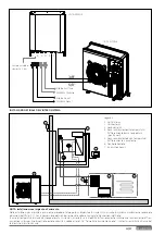
Page 17: ...onnessioni Elettriche In caso di temperatura di mandata troppo elevata il sistema si arresterà sia in modalità di funzionamento sanitario che riscaldamento raffres camento e sul dispositivo di controllo remoto apparirà il codice errore 116 Termostato pavimento aperto Il sistema ripartirà alla chiusura del termostato a riarmo manuale VE 1 6 4 5 2 3 7 Legenda 1 Unità Interna 2 Unità esterna 3 Sonda ...

Page 18: ...rezza dell installazione È inoltre vietato utilizzare per la messa a terra del sistema i tubi di collegamento idraulico e dell impianto di riscaldamento Il costruttore non è responsabile di eventuali danni provocati da un impianto con messa a terra inadeguata o da anomalie a livello dell impianto elettrico Connettere il cavo di alimentazione ad una rete 230V 50Hz 1ph o 400V 50Hz 3 ph verificando il...

Page 19: ...tabili sul mercato in modo da assicurarsi che essi non vadano in contatto con il compressore e i tubi caldi Per assicurarsi una corretta tenuta alla trazione i cavi elettrici devono essere bloccati utilizzando i pressacavi che si trovano sulla staffa D Collegare il cavo di comunicazione alle due unità seguendo le indicazioni presenti sulle morsettiere interna ed esterna In accordo con le istruzion...

Page 20: ...e fotovoltaica è mag giore di una soglia impostabile sul contabilizzatore HV IN 1 Ingresso a 230V Selezionare la modalità operativa tramite il parametro 17 1 0 EDF tariffa elettrica ridotta applicando in segnale a 230V all ingresso della morsettiera il bollitore sanitario è riscaldato secondo le modalità HC HP o HC HP 40 C selezionabili dal parametro 17 5 2 SG Ready 1 segnale 1 per il protocollo S...

Page 21: ...con GND sulla morsettiera dell unità esterna Collegare A sulla morsettiera dell unità interna con A sulla morsettiera dell unità esterna Collegare B sulla morsettiera dell unità interna con B sulla morsettiera dell unità esterna ANODE SE TNK BUS TA 1 TA 2 MOD BUS GND A B B T IN AUX1 24V 30mA 3G 4 mm 3G 4 mm 0 5 mm T N XXA ON OFF N XXA N 30mA T N ON OFF XXA N N XXA 1 ph 3 ph NOTA Si raccomanda di v...

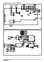
Page 22: ...22 IT SCHEMA ELETTRICO QUADRO UNITÀ ESTERNA 3 ph 1 ph ...

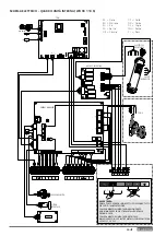
Page 23: ...2 CN11 F1 1 1 1 1 4 3 1 6 1 1 1 1 1 1 POWER OUT POWER IN SYSTEM INTERFACE BACK UP INTERFACE TDM ENERGY MANAGER PRESSURE SWITCH ELECTRICAL RESISTANCE SAFETY THERMOSTAT BU YE GN BN YE GN YE GN YE GN BN BU BN YE GN BU PUMP CN14 CN10 CN13 CN6 CN7 CN12 CN9 CN8 CN11 N N L 3 2 3 1 L L WH RD RD BK BN RD GN GY YE PI GN GN GY GY RD RD BU BU BU OR BK 230V L N L N BK Nero BN Marrone BU Blu RD Rosso OR Arancio...

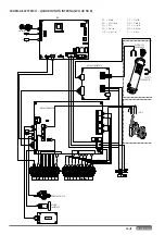
Page 24: ...N11 F1 1 1 1 1 4 3 1 6 1 1 1 1 1 1 POWER OUT POWER IN SYSTEM INTERFACE BACK UP INTERFACE TDM ENERGY MANAGER PRESSURE SWITCH ELECTRICAL RESISTANCE SAFETY THERMOSTAT BU YE GN YE GN BN YE GN YE GN YE GN BN BU BN YE GN BU PUMP CN14 CN10 CN13 CN6 CN7 CN12 CN9 CN8 CN11 N N L 3 2 3 1 L L WH RD RD BK BN RD GN GY YE PI GN GN GY GY RD RD BU BU BU OR BK 230V L N L N BK Nero BN Marrone BU Blu RD Rosso OR Aran...

Page 25: ... VALVE 1 VALVE 2 PUMP 1 FUSE 230V SERIAL ANODE PWM2 PWM1 CN7 SW1 CN6 CN1 CN4 CN13 CN9 CN5 CN14 CN2 CN8 EBUS B T EBUS C35 PUMP 2 CN10 CN16 CN12 CN11 F1 1 1 1 1 4 3 1 6 1 1 1 1 1 1 POWER OUT POWER IN SYSTEM INTERFACE BACK UP INTERFACE TDM ENERGY MANAGER PRESSURE SWITCH ELECTRICAL RESISTANCE SAFETY THERMOSTAT BU YE GN BN YE GN YE GN YE GN YE GN BN BU BN YE GN BU PUMP CN14 CN10 CN13 CN6 CN7 CN12 CN9 C...

Page 26: ... essere ef fettuato prima del collegamento alla linea BUS prima di collegare i fili alla base dell interfaccia di sistema far scor rere la linguetta di protezione del connettore e sollevarla fig 1 collegare la coppia di fili al connettore come spiegato nella pagina seguente e richiudere la linguetta di protezione fig 2 aprire i fori necessari per il fissaggio fissare la base dell apparecchio alla scatol...

Page 27: ...Funzionamento manuale Temperatura ambiente desiderata Temperatura ambiente rilevata Temperatura ambiente desiderata deroga Temperatura esterna Funzione AUTO attiva Funzione VACANZA attiva Riscaldamento attivo Sanitario attivo Segnalazione errore Menu completo Prestazioni sistema Opzioni schermo Impianto a pavimento Circolatore Valvola deviatrice ST1 Termostato impianto a pavimento Funzione antigel...

Page 28: ...sanitario durante l integrazione dall impianto foto voltaico Premere il tasto OK Ruotare la manopola e selezionare 17 1 Configurazione Ingressi Uscite Premere il tasto OK Ruotare la manopola e selezionare 17 1 0 HV IN 1 ingresso configurabile a 230V 0 Non definito nessuna funzione associata all ingresso Errore 941 visualiz zato sull interfaccia di sistema 1 Assente ingresso non attivo 2 EDF tariffa e...

Page 29: ...REEN NOTA utilizza solo la pompa di calore nei periodi definiti nella programmazione oraria ausiliaria sanitaria 17 5 3 Massimo tempo di caricamento Definisce il tempo di carica effettuato solo con la pompa di calore scaduto il quale vengono accese le resistenze di integrazione Premere il tasto OK Ruotare la manopola e selezionare 17 5 4 Funzione di Sanificazione Termica Premere il tasto OK Ruotare l...

Page 30: ...uito frigorifero Ruotare la manopola e selezionare 17 9 Statistiche 17 10 Diagnostica Pompa Calore 1 17 11 Diagnostica Pompa Calore 2 17 12 Diagnostica Pompa Calore 3 17 13 Diagnostica Pompa Calore 4 Visualizzano i valori delle grandezze caratteristiche della pompa di calore Ruotare la manopola e selezionare 17 14 Diagnostica scheda 1 ingresso Visualizza i valori degli ingressi della scheda di sis...

Page 31: ... la manopola e selezionare 4 2 3 Spostamento Parallelo Premere il tasto OK Ruotare la manopola ed impostare il valore più idoneo Premere il tasto OK per confermare IMPORTANTE Se la temperatura ambiente risulta maggiore del valore desiderato bisogna traslare parallelamente la curva verso il basso Se invece la temperatura ambiente risulta minore bisogna traslarla parallelamente verso l alto Se la te...

Page 32: ...a temperatura esterna estate si possono verificare tre condizioni 1 la temperatura ambiente aumenta questo indica che bisogna im postare una curva con minore pendenza 2 la temperatura ambiente diminuisce questo indica che bisogna im postare una curva con maggiore pendenza 3 la temperatura ambiente rimane costante questo indica che la cur va impostata ha la pendenza giusta Trovata la curva che manti...

Page 33: ...a Fissa di Mandata Dispositivi ON OFF Solo Sonda Ambiente Solo Sonda Esterna Sonda Ambiente Sonda Esterna Dispositivi ON OFF 4 2 2 Curva Termoregolazione 0 2 1 LT 1 3 5 HT 0 6 LT 1 5 HT 4 2 3 Spostamento Parallelo 14 14 HT 7 7 LT 0 C 4 2 4 Influenza Ambiente Proporzionale 0 20 C 2 C LT 10 C HT 4 2 5 Max T 20 C 45 C LT 20 C 70 C HT 45 C LT 60 C HT 4 2 6 Min T 20 C 45 C LT 20 C 70 C HT 20 C LT 20 C H...

Page 34: ...arametro generico zona 5 2 Impostazioni Zona 2 5 2 0 Range Temperatura Bassa Temperatura Alta Temperatura Bassa Temperatura 5 2 1 Selezione Tipologia Termoregolazione Temperatura Fissa di Mandata Dispositivi ON OFF Solo Sonda Ambiente Solo Sonda Esterna Sonda Ambiente Sonda Esterna Dispositivi ON OFF 5 2 2 Curva Termoregolazione 0 2 C 1 C LT 1 C 3 5 C HT 0 6 C LT 1 5 C HT 5 2 3 Spostamento Paralle...

Page 35: ...tivazione modo manuale OFF ON OFF 7 1 1 Controllo pompa Z1 OFF ON OFF 7 1 2 Controllo pompa Z2 OFF ON OFF 7 1 4 Controllo valvola mix Z2 OFF Aperto Chiuso OFF 7 2 Modulo di zona 7 2 0 Schema idraulico Non definito MCD MGM II MGM III MGZ I MGZ II MGZ III MGM II 7 2 1 Correzione T Mandata 0 40 0 7 2 2 Funzione uscita AUX Richiesta Calore Pompa esterna Allarme Richiesta Calore 7 2 3 Correzione Tempera...

Page 36: ...sta di calore esterna Nessuno 17 1 5 Uscita AUX 2 Nessuno Allarme fault Allarme umidostato Richiesta di calore esterna Nessuno 17 1 6 Impostazioni circ AUX P2 Circolatore ausiliario Circolatore per raffrescamento Circolatore ausiliario 17 2 Impostazioni 1 17 2 0 Schema Idraulico Nessuno Plus Compact Flex Nessuno 17 2 1 Termoregolazione Assente Presente Presente 17 2 2 Modalità riscaldamento Eco Pl...

Page 37: ...OFF 17 5 5 Orario attivazione sanificazione termica hh mm 00 00 24 00 01 00 17 6 Modo manuale 1 17 6 0 Attivazione modalità manuale OFF ON OFF 17 6 1 Circolatore Primario OFF Velocità bassa Velocità alta OFF 17 6 2 Valvola Deviatrice Sanitario Riscaldamento Sanitario 17 6 3 Valvola Deviatrice Raffrescamento Riscaldamento Raffrescamento Riscaldamento 17 6 4 Circolatore Ausiliario OFF ON OFF 17 6 5 C...

Page 38: ...ompa calore n 10 sola lettura 17 9 2 Ore di funz resistenza 1 h 10 sola lettura 17 9 3 Ore di funz resistenza 2 h 10 sola lettura 17 9 4 Ore di funz resistenza 3 h 10 sola lettura 17 9 5 Cicli resistenza 1 n 10 sola lettura 17 9 6 Ore di sbrinamento h 10 sola lettura 17 9 7 Ore funzionamento in raffr h 10 17 9 8 Ore funzionamento in risc h 10 17 9 9 Ore funzionamento in sanitario h 10 17 10 Diagno...

Page 39: ...ettura 17 11 7 Pressione condensatore sola lettura 17 11 8 Ultimo errore inverter sola lettura 17 12 Diagnostica Pompa Calore 3 17 12 0 Capacità Inverter 0 15 kW sola lettura 17 12 1 Frequenza attuale compressore 0 1100 Hz sola lettura 17 12 2 Modulazione del Compressore 0 100 sola lettura 17 12 3 Stato Riscaldatore elettrico sola lettura 17 12 5 Velocità ventilatore 1 0 1000 rpm sola lettura 17 1...

Page 40: ... 14 7 Stato Ingresso HV IN 2 sola lettura 17 14 8 Stato Ingresso HV IN 3 sola lettura 17 14 9 Ingresso AUX 1 Aperto Chiuso sola lettura 17 15 Diagnostica scheda 2 Uscite 17 15 0 Cancella impostazioni di fabbrica sola lettura 17 15 1 Stato circolatore ausiliario sola lettura 17 15 2 Valvola 3 vie Risc San sola lettura 17 15 3 Valvola 3 vie Risc Raffr sola lettura 17 15 4 Resistenza backup risc 1 so...

Page 41: ...i funzionamento del sistema installato In particolare consegnare all utilizzatore il manuale d istruzioni infor mandolo della necessità di conservarlo in prossimità dell apparecchio Informare inoltre l utilizzatore sulla necessità di procedere con le se guenti azioni Controllare periodicamente la pressione dell acqua di impianto Riportare in pressione il sistema disareandolo quando necessario Rego...

Page 42: ...2 0 9 41 HV IN1 non definito Funzione non selezionata tramite il parametro 17 1 0 9 42 HV IN2 non definito Funzione non selezionata tramite il parametro 17 1 1 9 44 Sovratemperatura in raffrescamento Controllare il flusso nel circuito raffrescamento 9 45 Flussostato incollato Controllare se il circolatore principale è attivo prima della richiesta calore Controllare il flusso con il valore flussimetro t...

Page 43: ... 922 Errore SST troppo bassa x 917 Errore congelamento temperature LWT e o TR troppa bassa x 951 Errore sovratemperatura TD x 950 Errore sovratemperatura TD x 918 Errore ciclo recupero refrigerante 919 Errore SDT troppo alta x 931 Errore inverter ERRORE INVERTER DESCRIZIONE 1ph 3ph 1 Sovratemperatura Dissipatore x x 2 Sovracorrente IPM Compressore x 3 Start up Compressore Fallito x 4 Sovracorrente...

Page 44: ...archio 2 Modello 3 Dati riscaldamento 4 Prestazione nominale riscaldamento 5 Dati raffrescamento 6 Prestazione nominale raffrescamento 7 Tipo olio del circuito frigorifero 8 Tipo di refrigerante carico del refrigerante 9 GWP indice del potenziale di riscaldamento globale 10 Equivalente CO2 11 Dati elettrici 12 Protezione elettrica 13 Potenza elettrica massima 14 Pressione massima circuito frigorif...

Page 45: ...r lateral passages 48 Internal unit Minimum clearance 49 Opening procedure for lateral passages 49 Safety valve drain 49 Connections between internal unit And external unit 50 Hydraulic fittings Internal unit 1 zone 51 Internal unit 2 zone 51 Electrical wiring Electrical circuit 52 External unit electrical connection 53 Electrical connections of the internal unit 54 Electrical scheme 55 Installatio...

Page 46: ...ectrical cur rent passing through undersized cables Protect all connection pipes and wires in order to prevent them from being damaged Electrocution caused by contact with live wires Flooding caused by water leaking from damaged piping Make sure the installation site and any systems to which the appliance must be connected comply with the applicable norms in force Electrocution caused by contact w...

Page 47: ...d equipment in such a way as to make movement easy and safe avoiding the formation of any piles which could yield or collapse Damage to the appliance or surrounding objects from shocks knocks incisions and squashing All operations inside the appliance must be per formed with the necessary caution in order to avoid abrupt contact with sharp parts Personal injury caused by cuts puncture wounds and a...

Page 48: ...place ment product is purchased The user is responsible for the disposal of the product at the end of its life at an appropriate waste disposal centre The waste disposal centre which using special treatment and recycling processes effectively dismantles and disposes of the appliance helps to protect the environment by recy cling the material from which the product is made For further information a...

Page 49: ...es please refer to the product catalogue EXTERNAL UNIT As external unit one of the following models is provided NIMBUS 40 S EXT NIMBUS 50 S EXT NIMBUS 70 S EXT NIMBUS 70 S T EXT NIMBUS 90 S T EXT NIMBUS 110 S T EXT EXTERNAL UNIT Weight 40 S EXT 52 50 S EXT 52 70 S EXT 82 70 S T EXT 90 90 S T EXT 110 110 S T EXT 110 Weights and dimensions mm 40 50 S EXT 756 383 1016 670 ø 10 374 ...

Page 50: ...50 GB 1106 383 1016 670 ø 10 374 1506 383 1016 670 ø 10 374 70 S 70 S T EXT 90 110 S T EXT ...

Page 51: ... air purge 12 Flow meter 13 Heating back up resistance 14 Safety thermostat manual switch 15 Safety thermostat automatic switch 16 Temperature sensor flow to the installation heating cooling INTERNAL UNIT Weights and dimensions mm Overall view A Hot cold water flow to the installation G 1 M B Cold Hot water return from the installation G 1 M C Gas connection from the external unit 5 8 M D Gas conn...

Page 52: ...or the electrical hookup refer to Electrical circuit Warning in case of installation of thermostatic valves on all terminals or zone valves install a bypass to ensure the minimum operating flow rate 43 22 43 5 10 5 10 22 0 5 10 15 20 25 0 5 10 15 20 25 30 35 40 45 50 A B 20 45 10 60 35 60 35 33 15 20 20 20 0 10 20 30 40 50 60 70 30 20 10 0 10 20 30 40 B A 0 100 200 300 400 500 600 700 800 0 500 10...

Page 53: ...and away from direct sunlight Remove the cover and install the sensor using the rawl plug and screw provided Perform connection using a 2x0 5 mm2 wire Maximum connection length 50 m Connect the wire to the terminal by introducing it from the lower part after creating a suitable passage Place the sensor cover back in the correct position A B C PRODUCT FICHE valid from September 26th 2015 SUPPLIER S...

Page 54: ...it as shown on the data plate of this unit EN 61000 3 12 Check that safety switches are correctly sized and connected to the external unit Choice of placement Avoid a mounting where the ODU is surrounded by walls Avoid a mounting in sinks Cold air sinks down and by that air short circuit could occur Avoid positioning the external unit in places which are dif ficult to access for the subsequent ins...

Page 55: ...g procedure for lateral passages To allow the passage of cables remove with the help of a screwdriver the precut parts A of the chassis of the external unit To effectively remove the material keep the front panel of the unit installed Prior to the passage of the cables place the black grommets B provided within the document envelope A B A The precutted holes for the passage of pipes are 4 1 on the...

Page 56: ... 2 Safety valve drain Assemble the drain pipe of the safety valve included in the pac kage documents 3 Flling system The maximum heating cooling system pressure is 3 bar The maxi mum filling pressure is 1 2 bar As soon as the system is filled disconnect it from the water mains Do not refill the system frequently multiple times a month as this can result in corrosion Expansion vessel The system is equ...

Page 57: ...acuum pump 8 Keep this status for 2 minutes while checking that compound gauge s pointer does not return 9 Detach the vacuum pump 10 Tightly secure the valve and caps of the service port 11 Replace caps and check for leaks by using a leak detector specific for HFC refrigerants After the leak check fully open the three way valve CAUTION Do not discharge the refrigerant gas to the atmosphere Use a va...

Page 58: ...never harder than 20 F 11 2 dH or softer than 12 F 6 7 dH and that its pH is 6 6 to 8 5 If this is not the case install water treatment to prevent incrustations and corrosion in system the water circuit pressure never exceeds 5 bar otherwise install a pressure reducer at the system s intake a disconnector with cock is installed between the system and the domestic water circuit if present the suppl...

Page 59: ...alve 3 bar EXTERNAL UNIT FINAL INSTALLATION OF THE WHOLE SYSTEM NOTE Installation with under floor systems For under floor installations make sure to install a safety device on the heating delivery circuit as required by DTU 65 11 For the thermostat hookup refer to Electrical connections If the delivery temperature is too high the system stops in both domestic hot water and heating cooling modes and...

Page 60: ...connection Electrical circuit Check that the voltage and frequency of power supply from the network coincide with the data shown in the data plate of the appliance see table In order to ensure greater security the main electrical system should be checked by a qualified technician before proceeding with the installation see note The manufacturer is not liable for any damage caused by installation w...

Page 61: ... the market in order to be sure that they will not be in contact with the compressor and the hot pipes To ensure good tensile strength the electric cables must be fastened using the cable holder on the plate D Connect the communication cable to the terminals as identified by their respective numbers on the terminal block of indoor and outdoor unit According to the installation instructions all dev...

Page 62: ...ode by the parameter 17 1 0 EDF Night tariff applying a 230V signal to the input the tank charge is enabled according to the DHW modes HC HP or HC HP 40 C selectable by the parameter 17 5 2 SG Ready 1 input signal nr 1 for the SG Ready standard see paragraph SMART GRID READY STANDARD HV IN 2 230V Input Select the operation mode by the parameter 17 1 1 DLSG load shedding this input signal if suppli...

Page 63: ...trical connections between internal and external units must be performed using the three low voltage terminals GND A B Connect GND on the terminal block of the internal unit with GND on the external terminal block Connect A terminal block on the internal unit with A on the external terminal block Connect B terminal block on the internal unit with B on the external terminal block NOTE It is strongl...

Page 64: ...64 GB 3 ph 1 ph ELECTRICAL SCHEME BOX OF EXTERNAL UNIT ...

Page 65: ... 2 CN10 CN16 CN12 CN11 F1 1 1 1 1 4 3 1 6 1 1 1 1 1 1 POWER OUT POWER IN SYSTEM INTERFACE BACK UP INTERFACE TDM ENERGY MANAGER PRESSURE SWITCH ELECTRICAL RESISTANCE SAFETY THERMOSTAT BU YE GN BN YE GN YE GN YE GN BN BU BN YE GN BU PUMP CN14 CN10 CN13 CN6 CN7 CN12 CN9 CN8 CN11 N N L 3 2 3 1 L L WH RD RD BK BN RD GN GY YE PI GN GN GY GY RD RD BU BU BU OR BK 230V L N L N BK Black BN Brown BU Blue RD ...

Page 66: ...N10 CN16 CN12 CN11 F1 1 1 1 1 4 3 1 6 1 1 1 1 1 1 POWER OUT POWER IN SYSTEM INTERFACE BACK UP INTERFACE TDM ENERGY MANAGER PRESSURE SWITCH ELECTRICAL RESISTANCE SAFETY THERMOSTAT BU YE GN YE GN BN YE GN YE GN YE GN BN BU BN YE GN BU PUMP CN14 CN10 CN13 CN6 CN7 CN12 CN9 CN8 CN11 N N L 3 2 3 1 L L WH RD RD BK BN RD GN GY YE PI GN GN GY GY RD RD BU BU BU OR BK 230V L N L N BK Black BN Brown BU Blue R...

Page 67: ...CN1 VALVE 1 VALVE 2 PUMP 1 FUSE 230V SERIAL ANODE PWM2 PWM1 CN7 SW1 CN6 CN1 CN4 CN13 CN9 CN5 CN14 CN2 CN8 EBUS B T EBUS C35 PUMP 2 CN10 CN16 CN12 CN11 F1 1 1 1 1 4 3 1 6 1 1 1 1 1 1 POWER OUT POWER IN SYSTEM INTERFACE BACK UP INTERFACE TDM ENERGY MANAGER PRESSURE SWITCH ELECTRICAL RESISTANCE SAFETY THERMOSTAT BU YE GN BN YE GN YE GN YE GN YE GN BN BU BN YE GN BU PUMP CN14 CN10 CN13 CN6 CN7 CN12 CN...

Page 68: ...e remote control Wall installation The Sensys system interface must be fitted to the wall before the BUS line is connected connect the pair of wires to the connector fig 1 open up the holes required for fixing fix the base of the device to the box on the wall using the screws supplied in the kit fig 2 position the system interface on the base pushing it gently downwards fig 3 Connection to the installat...

Page 69: ...detected Desired room temperature override Outdoor temperature AUTO function enabled HOLIDAY function enabled Central heating active Domestic hot water active Error indication Menu System performance Screen setting Floor Heating Circulation pump Valvola deviatrice ST1 Under floor heating system thermostat Anti frost function Thermal Cleanse Function Configurable device Heat pump Heating element 1 He...

Page 70: ...7 0 0 CH mode Press the OK button to confirm Turn the knob and select 0 Green excludes the electric resistances for the integration of the he ating 1 Standard Press the OK button to confirm Turn the knob and select 17 0 1 Quiet Mode Activation Press the OK button to confirm Turn the knob and select ON active function to reduce noise OFF Press the OK button to confirm Turn the knob and select 17 0 ...

Page 71: ...Pump Overrun Post circulation time 17 3 7 Max PWM Pump Circulator max speed 17 3 8 Min PWM Pump Circulator min speed 17 3 9 Floor drying Flow Set Point Temperature Define the flow setpoint temperature for the floor heating see parametre17 8 1 Push OK button Turn the knob and select 17 4 Cooling Press the OK button Turn the knob and select 17 4 0 Cooling mode activation Press the OK button Turn the...

Page 72: ...perature of 55 C for 6days and then with variable temperature from 25 C to 55 C for the fol lowing 18 days 15 20 25 30 35 40 45 50 55 60 0 5 10 15 20 25 30 4 Curing Heating Functional Heating floor drying done with variable temperature from 25 C to 55 C for the first 18 days and then at fixed temperature of 55 C for the following 6 days 15 20 25 30 35 40 45 50 55 60 0 5 10 15 20 25 30 5 Manual flo...

Page 73: ...rve should be set 2 The temperature of the room may rise indicating that a gentler curve should be set 3 The temperature of the room remains constant indicating that the set curve is exactly right Once you have found the curve which maintains the room tem perature at a constant level check the actual temperature value Turn the knob and select 4 2 3 Offset Press the OK button Turn the knob and set ...

Page 74: ...mperature of the room may fall indicating that a stee per curve should be set 3 The temperature of the room remains constant indicating that the set curve is exactly right Once you have found the curve which maintains the room temperature at a constant level check the actual temperature value IMPORTANT If the room temperature is higher than the desired value the curve must be shifted downwards dec...

Page 75: ...oportional 0 20 C 2 C LT 10 C HT 4 2 5 Max T 20 C 45 C LT 20 C 70 C HT 45 C LT 60 C HT 4 2 6 Min T 20 C 45 C LT 20 C 70 C HT 20 C LT 20 C HT 4 3 Z1 Diagnostics 4 3 0 Room T only read 4 3 1 Room T setpoint only read 4 3 2 Flow temperature only read 4 3 3 Return temperature only read 4 3 4 Heat Request Z1 OFF ON only read 4 3 5 Pump Status OFF ON only read 4 4 Z1 Zone Module Settings 4 4 0 Zone pump...

Page 76: ...20 C 70 C HT 45 C LT 60 C HT 5 2 6 Min T 20 C 45 C LT 20 C 70 C HT 20 C LT 20 C HT 5 3 DIAGNOSTIC ZONE 2 5 3 0 Max Integral Action on Room Control only read 5 3 1 Z2 Diagnostics only read 5 3 2 Room T only read 5 3 3 Room T setpoint only read 5 3 4 Flow temperature OFF ON only read 5 3 5 Pump Status OFF ON only read 5 4 Z2 Zone Module Settings 5 4 0 Zone Pump Modulation Fixed Modulating on DeltaT ...

Page 77: ...ling 7 3 0 Flow_T_offset_Cool 0 6 C 0 C 7 8 Error History 7 8 0 Last 10 Errors 7 8 1 Reset Error List Reset OK Yes esc No 7 8 2 Last 10 Errors 2 7 8 3 Reset Error List 2 Reset OK Yes esc No 7 9 Reset Menu 7 9 0 Reset Factory Settings Reset OK Yes esc No 17 HP System Parameters 17 0 User Parameters 17 0 0 CH mode Mode Green Mode Standard Mode Green 17 0 1 Quiet Mode Activation OFF ON OFF 17 0 2 Qui...

Page 78: ...s 2 Stages 17 2 7 Pro Tech anode active OFF ON OFF 17 2 9 Antiblocking pump enable OFF ON 17 3 Central Heating 17 3 0 CH pump prerun time 30 255 sec 30 sec 17 3 1 Time for prerun new attempt 0 100 sec 90 sec 17 3 2 CH Pump Overrun 0 16 min 3 min 17 3 3 Pump Speed Control Low speed High speed Modulating Modulating 17 3 4 Delta T Pump Setpoint 5 20 C 5 C 17 3 5 Min Pressure 0 3 0 4 bar 0 4 bar 17 3 ...

Page 79: ...Manual Mode 2 17 7 0 Manual mode activation OFF ON OFF 17 7 1 Force Hp Heat OFF ON OFF 17 7 2 Force Hp Cool OFF ON OFF 17 7 3 Rating heating mode OFF ON OFF 17 7 4 Rating cooling mode OFF ON OFF 17 7 5 Compressor frequency setting 18 120 Hz 30 Hz 17 7 6 Fan 1 rpm setting 0 1000 rpm 0 rpm 17 7 7 Fan 2 rpm setting 0 1000 rpm 0 rpm 17 7 8 TDM aux output OFF ON OFF 17 8 Test Utilities 17 8 0 Air purge...

Page 80: ... Cooling Rating in Heat Mode Rating in Cooling Mode Freeze Protection Defrost High Temperature Protection Timeguard System Fail Hard System Fail Pump Down only read 17 11 1 HP Error 0 29 only read 17 11 3 Flowmeter 0 1200 l min only read l min 17 11 4 Flow Switch Open Closed only read 17 11 5 Inverter shut off protection OFF ON only read 17 11 6 PEVAP Evaporator Pressure P only read 17 11 7 PCOND ...

Page 81: ...rature only read C 17 14 5 Pressure Switch only read 17 14 6 HV Input 1 only read 17 14 7 HV Input 2 only read 17 14 8 HV Input 3 only read 17 14 9 AUX Input 1 Open Closed only read 17 15 Energy Manager Diagnostics 2 Output 17 15 0 CH Circulator Status only read 17 15 1 HC Pump 2 only read 17 15 2 PCM Diverter Valve CH DHW only read 17 15 3 PCM Diverter Valve 2 CH Cooling only read 17 15 4 CH Back...

Page 82: ... the appliance Also inform the user of the need to proceed with the following actions Periodically check the water pressure Pressurize the system when necessary providing an adequate air purge Adjust the parameters setting and devices in order to obtain a better functioning and a more economical management of the system Subcontract as provided by the rules periodic maintenance Antifreeze function ...

Page 83: ...ot defined Hydraulic scheme not selected by parameter 17 2 0 9 41 HIV IN1 not defined Function not selected by parameter 17 1 0 9 42 HIV IN2 not defined Function not selected by parameter 17 1 1 9 44 Cooling overtemperature Check water flow of the cooling circuit 9 45 Flow switch stuck Check if main circulation is active before the heat request Check the water flow detection by water flow sensor s...

Page 84: ... Service x 951 HP HIGH TD Error x 950 HP HIGH TD Service x 918 HP Pump Down Error 919 HP HIGH SDT Error x 931 HP INVERTER Error INVERTER ERROR DESCRIPTION 1ph 3ph 1 Heat Sink Overheat x x 2 Compressor Ipm Over Current x 3 Compressor Fail To Drive x 4 Compressor Over Current x x 5 Input Voltage Lack Of Phase x 6 Compressor Ipm Current Sampling Failure x 7 Compressor Drive Capacitors Precharge Failu...

Page 85: ...t 9 GWP indice del potenziale di riscaldamento globale 10 Equivalente CO2 11 Electrical data 12 Electrical protection 13 Maximum electric power 14 Maximum pressure refrigerant circuit 15 Minimum pressure refrigerant circuit 16 Plant of manufacturing 17 Protection rating 18 Certificate 19 Contact address 1 2 3 4 5 9 10 11 MAX MIN 12 Legend 1 Brand 2 Manufacturer 3 Appliance model Serial number 4 Co...

Page 86: ...86 IT ...

Page 87: ...87 IT ...

Page 88: ...420010759800 07 2016 Ariston Thermo SpA Viale Aristide Merloni 45 60044 Fabriano AN Italy Telefono 0732 6011 Fax 0732 602331 info it aristonthermo com ...

Reviews: