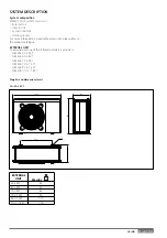
51 / GB
6
8
9
10
1
2
4 5
14
16
7
15
13
12
11
3
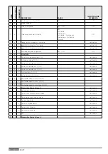
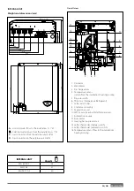
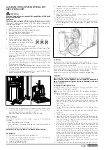
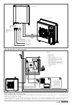
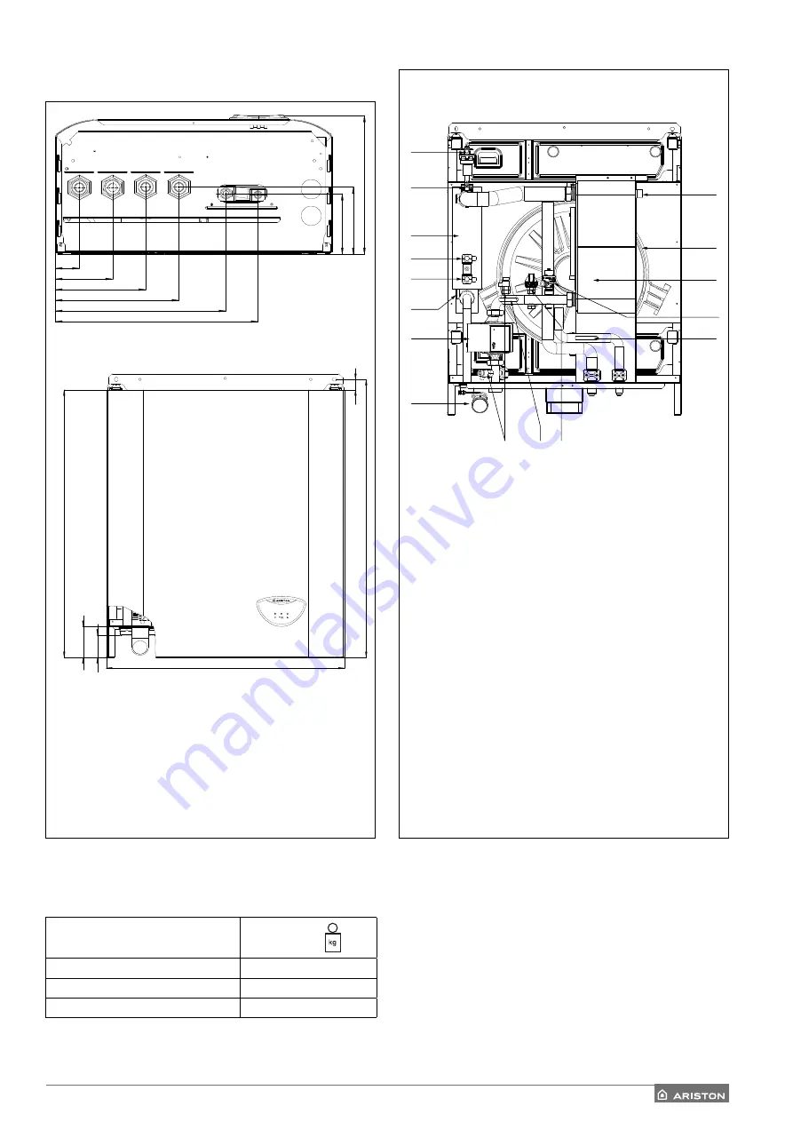
1. Circulator
2. Manometer
3. Discharge
valves
4. Temperature
sensor
(return from the installation) heating/cooling
5. Pressure
switch
6. TR Sensor (Temperature Refrigerant)
7. Safety valve 3 bar
8. Condenser
assembly
9.
Expansion vessel
10.
LWT Sensor (Leaving Water Temperature)
1
1. Automatic air purge
12. Flow meter
13. Heating back-up resistance
14. Safety thermostat (manual switch)
15. Safety thermostat (automatic switch)
16. Temperature sensor (fl ow to the installation)
heating/cooling
INTERNAL UNIT
Weights and dimensions (mm)
Overall view
A.
Hot/cold water fl ow to the installation G 1” M
B. Cold/Hot water return from the installation G 1” M
C.
Gas connection from the external unit 5/8” M
D.
Gas connection to the external unit 3/8” M
INTERNAL UNIT
Weight
WH 40 50 S
36
WH 70 S
37
WH 90 110 S
40
58
81
701
728
27
600
A
B
C
D
Summary of Contents for 3300919
Page 8: ...8 IT 1106 383 1016 670 ø 10 374 1506 383 1016 670 ø 10 374 70 S 70 S T EXT 9 0 110 S T EXT ...
Page 22: ...22 IT SCHEMA ELETTRICO QUADRO UNITÀ ESTERNA 3 ph 1 ph ...
Page 50: ...50 GB 1106 383 1016 670 ø 10 374 1506 383 1016 670 ø 10 374 70 S 70 S T EXT 90 110 S T EXT ...
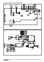
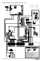
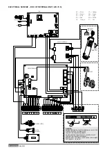
Page 64: ...64 GB 3 ph 1 ph ELECTRICAL SCHEME BOX OF EXTERNAL UNIT ...
Page 86: ...86 IT ...
Page 87: ...87 IT ...


