52 / GB
A -
Flow water temperature (°C)
B -
External air temperature (°C)
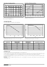
Restrictions of cooling operation
Restrictions of heating operation
AVAILABLE PRESSURE
Pressure available for distribution on the installation.
Available pressure
The curves indicated above show the available pressure of internal units.
In order to have a correct sizing of the system, the pressure drop curve of the entire circuit (in function of the nominal fl ow rate)
must stay below the available pressure curve everywhere. Pressure drop values depend on the specifi c installation.
You can install a supplementary circulation pump if the module’s own unit is not powerful enough. For the electrical hookup, refer
to «Electrical circuit».
Warning:
in case of installation of thermostatic valves on all terminals or zone valves, install a bypass to ensure the minimum
operating fl ow rate.
(43 ; 22)
(43 ; 5)
(10 ; 5)
(10 ; 22)
0
5
10
15
20
25
0
5
10
15
20
25
30
35
40
45
50
A
B
(-20 ; 45)
(-10 ; 60)
(35 ; 60)
(35 ; 33)
(15 ; 20)
(-20 ; 20)
0
10
20
30
40
50
60
70
-30
-20
-10
0
10
20
30
40
B
A
0
100
200
300
400
500
600
700
800
0 500
1000
1500
2000
mbar
l\h
0
100
200
300
400
500
600
700
800
0 500 1000 1500 2000 2500
mbar
l\h
System Size
Flowmeter OFF
Threshold [l/h]
Flowmeter ON
Threshold [l/h]
Nominal fl ow rate [l/h]
40 S EXT
280
360
640
50 S EXT
350
450
800
70 S EXT
490
630
1120
70 S-T EXT
490
630
1120
90 S-T EXT
630
810
1440
110 S-T EXT
770
990
1755
Available pressure for sizes:
: 40 S - 50 S - 70 S - 70 S-T EXT
Available pressure for sizes:
: 90 - 110 S-T EXT
1
Example: 1B = 35 and A = 33
Summary of Contents for 3300919
Page 8: ...8 IT 1106 383 1016 670 ø 10 374 1506 383 1016 670 ø 10 374 70 S 70 S T EXT 9 0 110 S T EXT ...
Page 22: ...22 IT SCHEMA ELETTRICO QUADRO UNITÀ ESTERNA 3 ph 1 ph ...
Page 50: ...50 GB 1106 383 1016 670 ø 10 374 1506 383 1016 670 ø 10 374 70 S 70 S T EXT 90 110 S T EXT ...
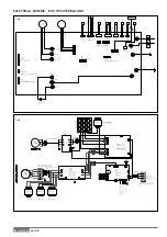
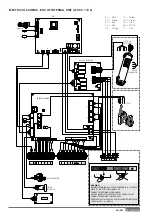
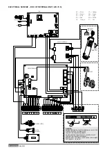
Page 64: ...64 GB 3 ph 1 ph ELECTRICAL SCHEME BOX OF EXTERNAL UNIT ...
Page 86: ...86 IT ...
Page 87: ...87 IT ...

