53 / GB
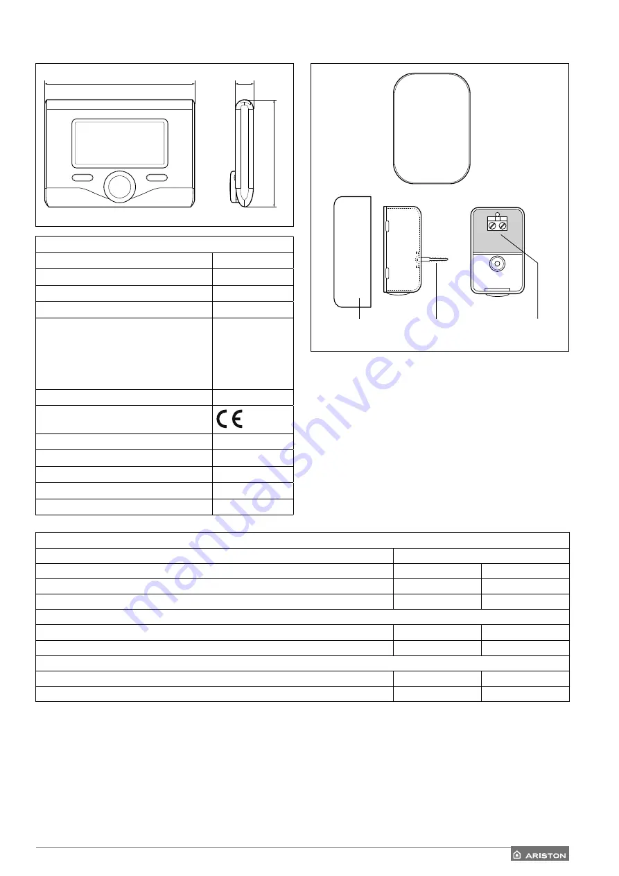
TECHNICAL DATA
Power supply
BUS
Electrical absorption
max. < 0,5W
Operating temperature
-10 ÷ 60°C
Storage temperature
-20 ÷ 70°C
Bus wire length and cross-sectional area
NOTE:
TO AVOID INTERFERENCE PROBLEMS,
USE A SHIELDED CABLE OR TWISTED
PAIR CABLE.
max. 50 m
min. 0.5 mm²
Buffer memory
2 h
Conformity
LVD 2014/35/EU - EMC 2014/30/EU
Electromagnetic interference
EN 60730-1
Electromagnetic emissions
EN 60730-1
Conformity to standards
EN 60730-1
Temperature sensor
NTC 5 k 1%
Resolution degree:
0,1°C
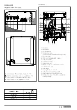
134 mm
16 mm
96 mm
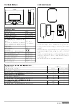
SYSTEM INTERFACE
OUTDOOR SENSOR
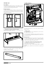
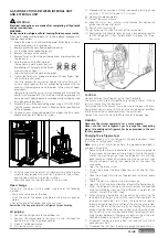
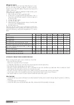
Position the outdoor sensor on the north-facing wall of the
building, at least 2.5 m from the ground and away from direct
sunlight.
Remove the cover and install the sensor using the rawl plug
and screw provided. Perform connection using a 2x0.5 mm2
wire.
Maximum connection length 50 m. Connect the wire to the
terminal by introducing it from the lower part after creating a
suitable passage.
Place the sensor cover back in the correct position.
A
B
C
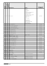
PRODUCT FICHE (valid from September 26th, 2015)
SUPPLIER’S NAME
ARISTON
SUPPLIER’S MODEL IDENTIFIER
SENSYS
OUTDOOR SENSOR
Class of the temperature control
V
II
Contribution to seasonal space heating energy effi
ciency in %
+3%
+2%
Adding an ARISTON OUTDOOR SENSOR:
Class of the temperature control
VI
--
Contribution to seasonal space heating energy effi
ciency in %
+4%
--
In a 3-zones system with 2 ARISTON ROOM SENSORS
Class of the temperature control
VIII
--
Contribution to seasonal space heating energy effi
ciency in %
+5%
--
Summary of Contents for 3300919
Page 8: ...8 IT 1106 383 1016 670 ø 10 374 1506 383 1016 670 ø 10 374 70 S 70 S T EXT 9 0 110 S T EXT ...
Page 22: ...22 IT SCHEMA ELETTRICO QUADRO UNITÀ ESTERNA 3 ph 1 ph ...
Page 50: ...50 GB 1106 383 1016 670 ø 10 374 1506 383 1016 670 ø 10 374 70 S 70 S T EXT 90 110 S T EXT ...
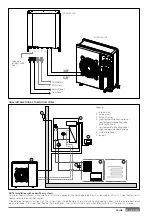
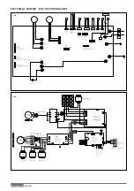
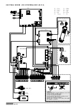
Page 64: ...64 GB 3 ph 1 ph ELECTRICAL SCHEME BOX OF EXTERNAL UNIT ...
Page 86: ...86 IT ...
Page 87: ...87 IT ...


