54 / GB
Warning
The appliance must be installed by a qualifi ed technician
in possession of the skills required by law.
Before installing the appliance
• The outdoor unit uses an ecological refrigerant liquid (type
HFC R-410A) that does not aff ect the integrity of the ozone
layer. Refrigerant R-410A operates at a pressure 50-70%
higher than refrigerant R22. Make sure that all the materials
used for maintenance and to fi ll the components can be
used with refrigerant R-410A.
• The bottles containing refrigerant R-410A are equipped with
a dip tube which allows the liquid to fl ow only when placed
in a vertical position with the valve in the upper position.
• The appliance should be fi lled with the indicated refrige-
rant R-410A. Apply a dispenser, available on the market, on
the pipe sleeve, in order to vaporize the refrigerant before it
fl ows in the external unit.
• The refrigerant R-410A, as all HFC fl uids, is only compatible
with the oils recommended by the compressor manufac-
ture.
• The vacuum pump is not suffi
cient to completely eliminate
the presence of humidity in the oil.
• POE type oils quickly absorb humidity. Do not expose oil to
air.
• Never open the appliance when it is in vacuum conditions.
• Do not throw the refrigerant R-410A in the environment.
• The oil contained in the compressor is extremely hygrosco-
pic.
• Ensure that, during the installation of the external unit, all
national regulations in terms of safety are observed.
• Make sure that the appliance is connected properly to the
ground. Check that the voltage and frequency of power sup-
ply match those necessary to the external unit and that the
installed capacity is suffi
cient to allow the functioning of the
appliance itself.
• Check that the impedance of the supply net corresponds to
the power input from the external unit as shown on the data
plate of this unit (EN 61000-3-12).
• Check that safety switches are correctly sized and connected
to the external unit.
Choice of placement
• Avoid a mounting where the ODU is surrounded by walls
• Avoid a mounting in sinks. Cold air sinks down and by that
air short circuit could occur.
• Avoid positioning the external unit in places which are dif-
fi cult to access for the subsequent installation and mainte-
nance.
• Avoid placing it near sources of heat.
• Avoid placing it in places where the external unit is subjec-
ted to continuous vibration.
INSTALLATION GUIDE
• Do not place the external unit on structures that do not gua-
rantee support.
• Avoid placing it in close proximity to fuel tanks of gas.
• Avoid a positioning that provides exposure to oil vapors.
• Avoid a positioning characterized by particular environmen-
tal conditions.
• Choose a location where noise and air discharged from the
outdoor unit will not disturb the neighbors.
• Choose a position sheltered from the wind.
• Provide a placement that allows the compliance to the re-
quired installation distances.
• Avoid placing it in a location that prevents access to ports
and / or passageways.
• The structure of the soil surface should be able to support
the weight of the external unit and reduce as much as pos-
sible vibrations.
• If the external unit is installed in a location where there are
abundant snowfall, install the unit at least 200 mm above
the usual level of fallen snow or use a support bracket.
WARNING:
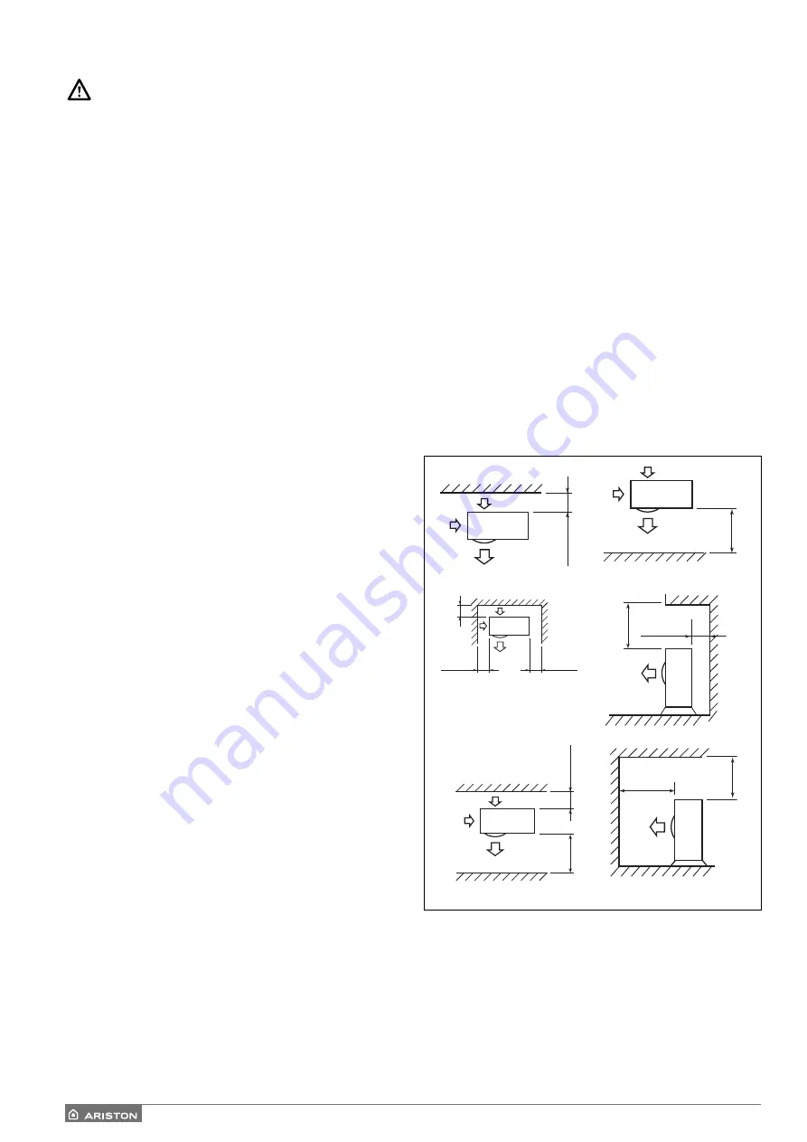
Defi ne where the units will be located taking into account the
minimum installation clearances in mm shown here above.
Note: The distances indicated here above are the minimum for
a good unit operation. To avoid abnormal noise, echoes and
resonances increase this distances especially on the front side
of the units. The height of the obstacles at both front and side
should be lower than the height of the outdoor unit.
150
500
150
300
150
500
150
1000
1000
1000
200
Minimum distances to installation (mm)
Summary of Contents for 3300919
Page 8: ...8 IT 1106 383 1016 670 ø 10 374 1506 383 1016 670 ø 10 374 70 S 70 S T EXT 9 0 110 S T EXT ...
Page 22: ...22 IT SCHEMA ELETTRICO QUADRO UNITÀ ESTERNA 3 ph 1 ph ...
Page 50: ...50 GB 1106 383 1016 670 ø 10 374 1506 383 1016 670 ø 10 374 70 S 70 S T EXT 90 110 S T EXT ...
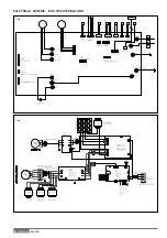
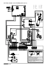
Page 64: ...64 GB 3 ph 1 ph ELECTRICAL SCHEME BOX OF EXTERNAL UNIT ...
Page 86: ...86 IT ...
Page 87: ...87 IT ...

