55 / GB
Attention
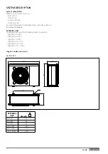
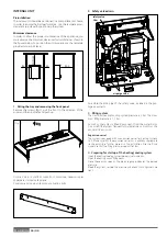
Before installation, check strength and horizontality of
the base. Based on the pictures, connect the base of the
external unit fi rmly to the ground, using suitable anchor
bolts (M10 x 2 pairs).
If the external unit should be exposed to signifi cant air
fl ow, protect the fan using a protective screen and verify
the proper positioning and functioning.
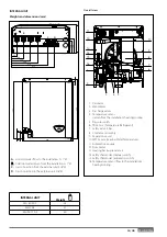
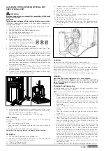
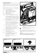
1. Opening procedure for lateral passages
To allow the passage of cables, remove, with the help of a
screwdriver, the precut parts (A) of the chassis of the external
unit. To eff ectively remove the material, keep the front panel of
the unit installed.
Prior to the passage of the cables, place the black grommets
(B) provided within the document envelope.
A
B
A
The precutted holes for the passage of pipes are 4:
1 on the right side (C)
1 on the back side (D)
2 on the base panels (E)
C
E
E
D
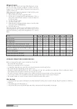
2. Removal of frontal panel
Remove the screws that block the frontal panel and pull it
forward and down.
Summary of Contents for 3300919
Page 8: ...8 IT 1106 383 1016 670 ø 10 374 1506 383 1016 670 ø 10 374 70 S 70 S T EXT 9 0 110 S T EXT ...
Page 22: ...22 IT SCHEMA ELETTRICO QUADRO UNITÀ ESTERNA 3 ph 1 ph ...
Page 50: ...50 GB 1106 383 1016 670 ø 10 374 1506 383 1016 670 ø 10 374 70 S 70 S T EXT 90 110 S T EXT ...
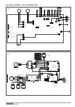
Page 64: ...64 GB 3 ph 1 ph ELECTRICAL SCHEME BOX OF EXTERNAL UNIT ...
Page 86: ...86 IT ...
Page 87: ...87 IT ...


