56 / GB
INTERNAL UNIT
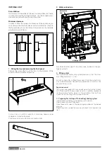
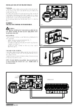
Preinstallation
The indoor unit should be positioned in a compartment at home,
in order to ensure the best performance. Use the template provi-
ded and a spirit level for positioning the system.
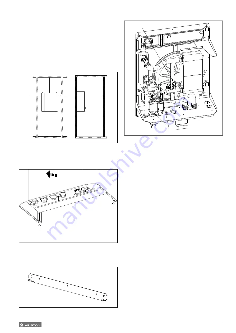
Minimum clearance
In order to allow the proper maintenance of the appliance, you
must observe the minimum clearances for installation as shown in
the fi gures below. To position the unit properly, use the template
provided and a spirit level.
50 50
500
MIN 350
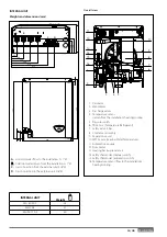
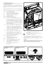
1. Fitting the tray and removing the front panel
Remove the screws (fi g.1), pull the front in the direction of the
arrow and then inclinate and push up
Fissare a muro la staffa di supporto in dotazione, necessaria per
appendere il modulo alla parete.
Posizionare il modulo utilizzando una livella a bolla.
(Fig. 1)
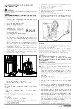
2. Safety valve drain
Assemble the drain pipe of the safety valve, included in the pac-
kage documents.
3. Flling system
The maximum heating/cooling system pressure is 3 bar. The maxi-
mum fi lling pressure is 1,2 bar.
As soon as the system is fi lled, disconnect it from the water mains.
Do not refi ll the system frequently (multiple times a month) as this
can result in corrosion.
Expansion vessel
The system is equipped with an expansion vessel for heating systems
(8 l). Make sure that the expansion vessel has a capacity appropriate
to the quantity of water present in the installation. Prior to fi lling,
make sure that the fi lling pressure is equal to 1 bar.
4. Preparing for startup of the heating/cooling system
Open the heating/cooling system delivery/return cocks.
Open the heating circuit fi lling cocks.
Close the cocks as soon as the pressure gauge indicates the desired
pressure.
Bleed the system, restore the pressure and check that all gaskets are
tight.
air purge valve
safety valve
3 bar
Summary of Contents for 3300919
Page 8: ...8 IT 1106 383 1016 670 ø 10 374 1506 383 1016 670 ø 10 374 70 S 70 S T EXT 9 0 110 S T EXT ...
Page 22: ...22 IT SCHEMA ELETTRICO QUADRO UNITÀ ESTERNA 3 ph 1 ph ...
Page 50: ...50 GB 1106 383 1016 670 ø 10 374 1506 383 1016 670 ø 10 374 70 S 70 S T EXT 90 110 S T EXT ...
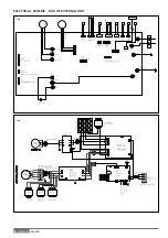
Page 64: ...64 GB 3 ph 1 ph ELECTRICAL SCHEME BOX OF EXTERNAL UNIT ...
Page 86: ...86 IT ...
Page 87: ...87 IT ...

